12
ADJUSTING CLAMPING ACTION OF BLADE HOLDERS
Different widths of scroll saw blades will make it necessary to adjust the clamping action of the blade holders. It should
be noted, however, that very little adjustment is necessary and very little clamping force is required to hold the blade
satisfactorily. As a rule of thumb, looking down at the table with the table insert slot in the 6 o’clock position, resistance
on the blade locking lever should be felt when the upper blade locking lever reaches the 7 o’clock position, or when
the lower blade locking lever reaches the 5 o’clock position.
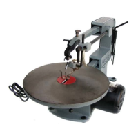
Fig. 21
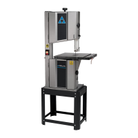
Fig. 22
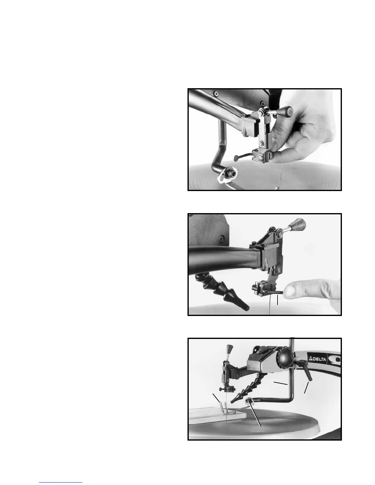
Fig. 23
ADJUSTING HOLDDOWN
1. The holddown (A) Fig. 23, should be adjusted so it
contacts the top surface of the work being cut by loos-
ening lock handle (B) and moving holddown rod (C) up or
down. Then tighten lock handle (B).
2. When bevel cutting (table tilted), the holddown (A)
Fig. 23, can be tilted to match the angle of the table by
loosening screw (D), tilting holddown (A) and tightening
screw (D).
1. Move the blade holder clamping lever (A) Fig. 21, to
the rear (open) position as shown.
2. Turn adjustment knob (B) Fig. 21, clockwise to tight-
en or counterclockwise to loosen the clamping action on
the blade holder. NOTE: Very little movement of the knob
(B) is necessary to make the adjustment.
A
B
A
C
D
3. Move lever (A) Fig. 22, forward after adjusting the
blade clamping action.
4. Adjust clamping action on lower blade holder in the
same manner.
 Loading...