10
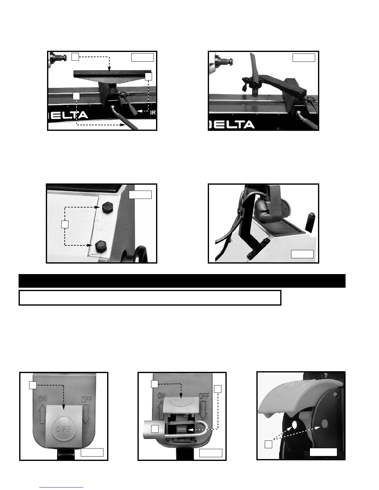
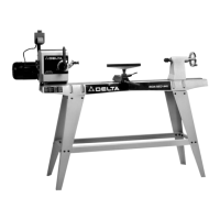
ADJUSTING CLAMP ON TOOL REST
To adjust the tool rest clamping action, use a 15/16" wrench to adjust the nut (A) Fig. 16 in the same manner as the headstock and
tailstock.
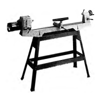
ATTACHING ON/OFF SWITCH TO TOOL
The "ON/OFF" switch comes unattached to the tool to protect it from damage in shipping. To attach the "ON/OFF" Switch:
1. Remove the two hex bolts (A) Fig. 19 that are attached to the back of the headstock, located near the top.
2. Align the two holes in the bottom of the "ON/OFF" switch with the two holes where the hex bolts were removed in STEP 1.
3. Secure the "ON/OFF" switch to the headstock with the bolts that were removed in STEP 1 (Fig. 20).
A
C
D
C
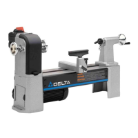
STARTING AND STOPPING THE TOOL
The power switch (A) Fig. 22, located under the safety cover (B) Fig. 21, provides electrical power to the adjustable speed drive.
Lift the safety cover (B) and move the switch up to the “ON” position. To turn the power off, push the safety cover (B) down.
NOTE: In case of emergency, immediately push the safety cover (B) down to shut off power.
LOCKING SWITCH IN THE “OFF” POSITION
IMPORTANT: When the tool is not in use, the switch should be locked in the “OFF” position to prevent unauthorized use, using a
padlock (C) Fig. 22, with a 3/16" diameter shackle inserted through the holes in the switch plate (D) Fig. 22B.
B
Fig. 17
Fig. 18
Fig. 19
Fig. 20
Fig. 21
Fig. 22
A
B
C
OPERATION
OPERATIONAL CONTROLS AND ADJUSTMENTS
D
Fig. 22B