3
Fig. 4
Fig. 6
Fig. 5
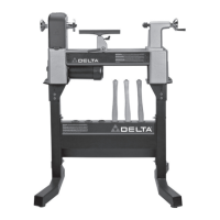
ASSEMBLING PLANER TO STAND
1. Carefully lift the planer (E) Fig. 5, onto the stand (B) as
shown. CAUTION: EXTREME CARE SHOULD BE TAKEN
WHEN LIFTING THE PLANER ONTO THE STAND AS
THE CUTTERHEAD KNIVES ARE EXTREMELY SHARP
AND THE PLANER IS VERY HEAVY. IF IT IS NOT DONE
MECHANICALLY, A MINIMUM OF FOUR PEOPLE ARE
REQUIRED TO MANUALLY LIFT THE MACHINE.
2. Align the four holes in the bottom of the planer (E)
Fig. 5, with the mounting holes in the top of stand (B), and
mount the planer to the stand with four M8 x 30MM hex
head screws (F) Fig. 5, lockwashers and flange nuts.
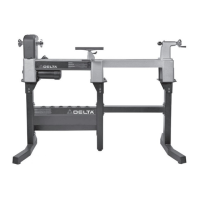
NOTE: Screws (F) Fig. 6, one of which is shown, are
started upward from the inside of stand (B). Later planer
models may not need flange nuts.
3. Once the planer is assembled to the stand, push
down on top of the planer so the legs of the stand adjust
to the floor surface. Tighten all stand mounting
hardware.
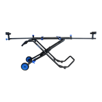
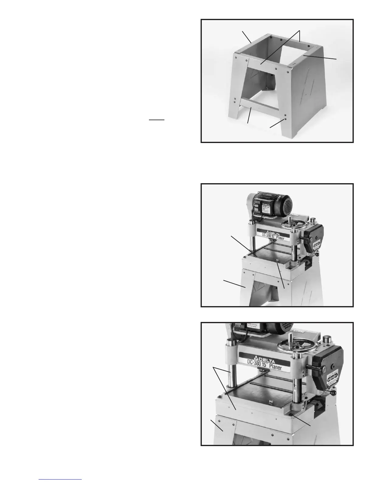
ASSEMBLING STAND
1. Assemble the two longer support brackets (A) Fig. 4,
one of which is shown, to the inside of end panels (B) with
eight 5/16-18 x 3/4″ carriage head screws (C), flat
washers, and 5/16-18 hex nuts. DO NOT COMPLETELY
TIGHTEN HARDWARE AT THIS TIME.
2. Assemble the two shorter support brackets (D) Fig. 4,
to the inside top of end panels (B) with the remaining
eight 5/16-18 x 3/4″ carriage head screws (C), flat washers
and 5/16-18 hex nuts. DO NOT COMPLETELY TIGHTEN
HARDWARE AT THIS TIME. NOTE: Make certain the top
lip of support brackets (D) are positioned under the top
lips of end panels (B) as shown in Fig. 4.
B
D
B
A
C
E
B
E
B
F
F
 Loading...