17
Fig. 30
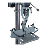
TABLE ADJUSTMENTS
1. The table can be raised or lowered on the column by
loosening table clamp handle (A) Fig. 29, and turning the
table raising and lowering handle (B). After the table is at
the desired height, tighten handle (A).
2. The table can be tilted right or left by pulling out and
removing table alignment pin (C) Fig. 30, and loosening
table locking bolt (D). Tilt the table to the desired angle
and tighten bolt (D). A tilt scale and pointer are provided
on the table bracket casting to indicate the degree of tilt.
When returning table to the level position, replace table
alignment pin (C) Fig. 30. This will automatically position
the table surface at 90 degrees to the spindle.
C
D
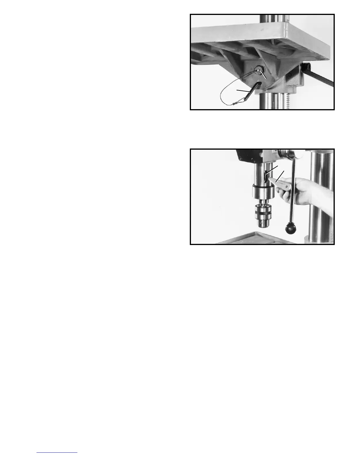
Fig. 31
REMOVING CHUCK
AND SPINDLE ADAPTER
If you desire to remove the chuck and spindle adapter,
lower spindle and rotate chuck until the slot in the
spindle lines up with the slot in the quill, as shown in
Fig. 31. Then insert tapered end of drift bar (A) into slot
(B) in quill and remove chuck and spindle adapter.
B
A
 Loading...