ASDA-A2 Chapter 6 Control Mode of Operation
Revision February, 2017 6-7
6.2.2 Position Command in PR Mode
PR position command source of each axis is from the 64-set of register which constituted by
parameters (P6-00, P6-01) ~ (P7-26, P7-27). Through communication, one of the 99-set of register
can be used as the position command. When going with the external DI/DO (CN1, POS0 ~POS5
and CTRG), one of the previous 64 sets of register can be selected as the position command. See
as the following table:
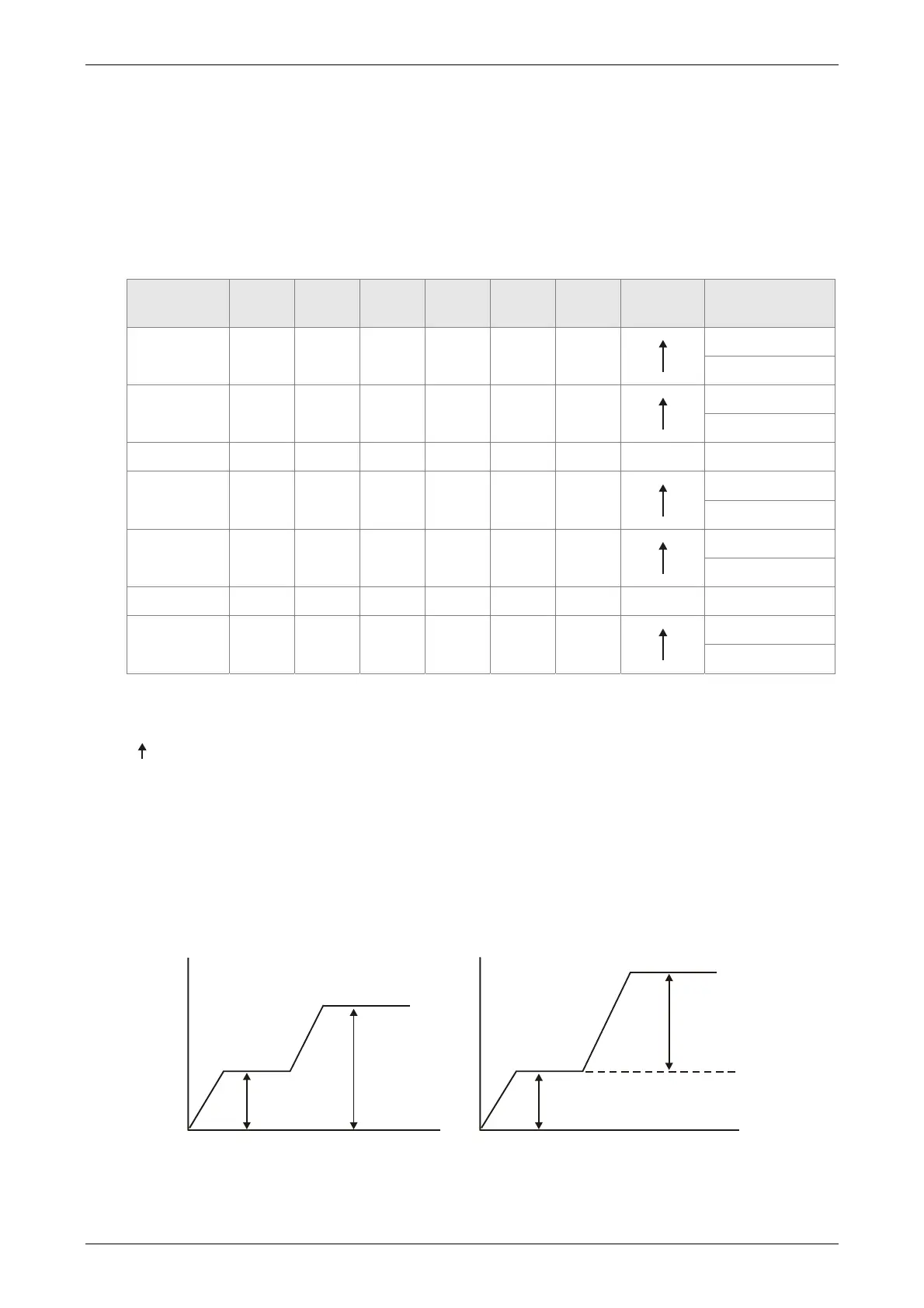
Position
Command
POS5 POS4 POS3 POS2 POS1 POS0 CTRG Parameters
P1 ON ON ON ON ON ON
P6-00
P6-01
P2 ON ON ON ON ON OFF
P6-02
P6-03
~ ~
P50 OFF OFF ON ON OFF ON
P6-98
P6-99
P51 OFF OFF ON ON OFF OFF
P7-00
P7-01
~ ~
P64 OFF OFF OFF OFF OFF OFF
P7-26
P7-27
Status of POS0 ~ POS5: 0 means the DI is OFF; 1 means the DI is ON.
CTRG
: the moment DI is OFF to ON.
The application of absolute type and incremental type register is rather extensive. It is more like a
simple procedure control. Users can complete the cyclic operation by referring to the above table.
For example, position command P1 is 10 turns and P2 is 20 turns. P1 is issued first and P2 comes
after. The following diagram shows the difference of both.
20 turns
10 turns
20 turns
10 turns
Absolute Type Incremental Type
 Loading...
