- 3 -
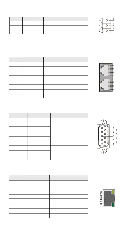
COM2 (RS-485)
DVP10MC11T offers one RS-485 port. See the table below for the PIN definitions.
PIN Signal Definition
1 + Signal+
2 _ Signal-
3 SG --
CANopen Communication Port
DVP10MC11T offers two RJ45 connectors as the interface for motion control. When
establishing a network, use standard CAN cables for the CAN bus, e.g. Delta TAP-CB03
or TAP-CB04. You will need termination resistances at the two ends of the bus, e.g.
Delta TAP-TR01.
PIN Signal Definition
1 CAN_H Signal+
2 CAN_L Signal-
3 CAN_GND 0 VDC
4 RESE_1 Reserved
5 RESE_2 Reserved
6 CAN_SHLD Shielded cable
7 CAN_GND 0 VDC
8 RESE_3 Reserved
Encoder Interface
DVP10MC11T offers one 9-PIN D-SUB encoder interface. See the table bellows for the
terminal definitions.
Terminal Signal Definition
1 A+
2 B+
3 Z+
6 A-
7 B-
8 Z-
Incremental encoder
4 +24VEXT
5 GNDEXT
24V encoder
9 +5VEXT +5V encoder
Ethernet Port
DVP10MC11T offers one Ethernet port, supporting Modbus/TCP protocol. See the table
below for the terminal definitions.
Terminal Signal Definition
1 Tx+ Sending data (positive)
2 Tx- Sending data (negative)
3 Rx+ Receiving data (positive)
4 -- N/C
5 -- N/C
6 Rx- Receiving data (negative)
7 -- N/C
8 -- N/C

 Loading...


