EasyManua.ls Logo

Delta DVP-MC Series User Manual

Delta DVP-MC Series
20 pages
To Next Page IconTo Next Page
To Previous Page IconTo Previous Page
Page #5 background image
- 4 -
Installation & Wiring
Installation
Install DVP10MC11T in an enclosure with sufficient
space around it to allow heat dissipation. D >
50mm (See the figure).
D
D
D
D
DVP10MC11T
Input Point Wiring
Mode Simplified model Wiring loop
Sink
Source
Output Point Wiring
All transistor outputs in DVP10MC11T include zener diode, which is sufficient enough for
small-power conductive load and infrequent On/Off applications. However, in big-power
or frequent On/Off occasions, follow the method below to connect to suppression circuit
to reduce interferences and avoid the transistor output circuit from being damaged due
to over-voltage or overheating.
[Figure 3]
24 VDC power supply Fuse
Emergency stop button Load: Switch, conductive load
9V Zener diode, 5W (Use and when in big-power and frequent On/Off occasions)
Diode or equivalent components for suppression (Use only when in small-power loads)
Connecting to DVP-S Series Extension Modules
Question and Answer IconNeed help?

Do you have a question about the Delta DVP-MC Series and is the answer not in the manual?

Delta DVP-MC Series Specifications

General IconGeneral
BrandDelta
ModelDVP-MC Series
CategoryController
LanguageEnglish

Summary

Product Profile and Dimensions

Model Name

Identifies the specific model of the Delta DVP-MC series motion controller.

Status Indicators

Details the POWER, RUN, ERR, COM1, COM2, CAN, and MTL status indicator lights.

Control and Interface Elements

Describes the RUN/STOP switch, RESET button, and various communication/expansion ports.

Mounting and Connectivity Features

Explains the DIN rail clip, extension module clip, and direct mounting holes.

Electrical Specifications

Power Supply Details

Covers voltage, fuse, insulation, consumption, and immunity for the device's power supply.

I/O Specifications

Details I/O channels, types, terminals, delay times, input current, and cable length.

COM Ports Overview

Provides pin definitions and signal assignments for COM ports (RS-232 and RS-485).

Communication and Interface Ports

CANopen Communication Port

Details the RJ45 connectors for CANopen communication, including termination requirements.

Encoder Interface

Explains the 9-PIN D-SUB encoder interface for incremental or 24V/5V encoders.

Ethernet Port

Describes the Ethernet port for Modbus/TCP protocol, including pin definitions.

Installation and Wiring Guidance

Installation Environment

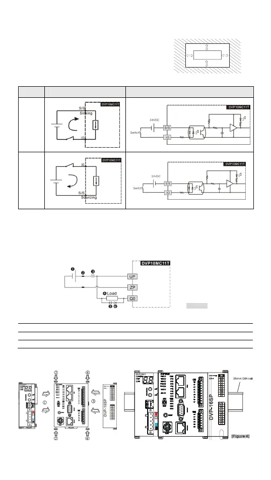
Recommends installing the device in an enclosure with sufficient space for heat dissipation.

Input Point Wiring

Illustrates simplified models and wiring loops for sink and source input configurations.

Output Point Wiring

Advises on connecting suppression circuits for big-power or frequent On/Off output applications.

Connecting Extension Modules

Shows how to connect the DVP10MC11T to DVP-S series extension modules.

LED Indicators and Troubleshooting

ERR LED Status and Corrections

Explains ERR LED states (Off, Red flashing, quick flashing) and their troubleshooting steps.

CAN LED Status and Corrections

Details CAN LED states (Green single flashing, flashing, constant, Red flashing, constant) and remedies.

MTL LED Status and Corrections

Covers MTL LED states (Off, Green on, flashing, Red constant, flashing) and troubleshooting.

Related product manuals