- 6 -
+24V
24G
S/S
X0
X1
[ Figure 6 ]
[Figure 5]
24G
+24V
S/S
X0
X1
[ Figure 5 ]
[Figure 6]
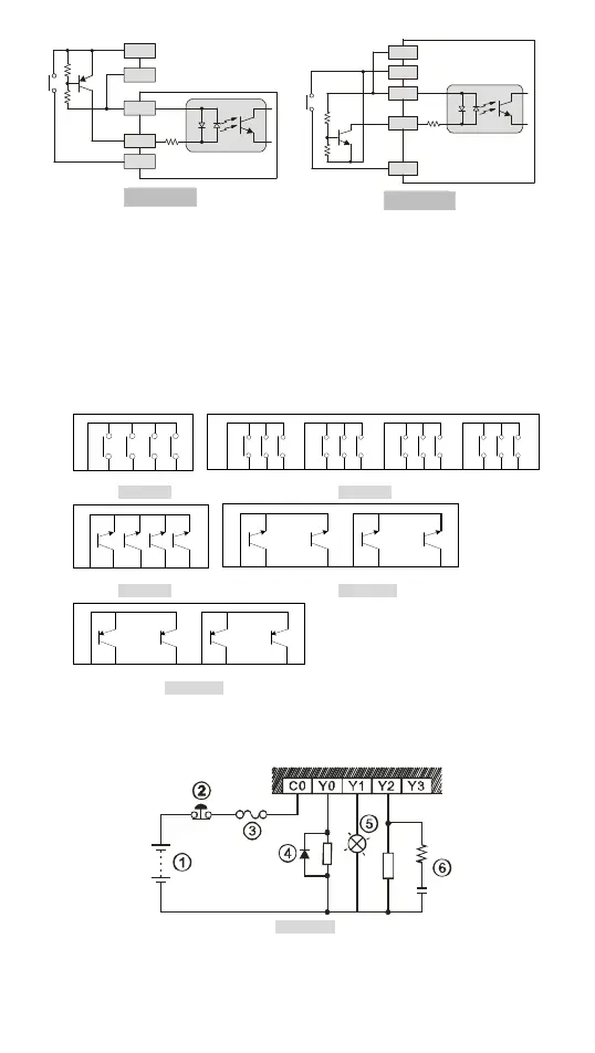
Output Point Wiring
1. DVP-SA2 has two output modules on it, relay and transistor. Be aware of the
connection of shared terminals when wiring output terminals.
2. Relay output terminals Y0 to Y3 of 12SA2 relay model use C0 common port. See
[Figure 7]. For 28SA211R relay model, see [Figure 8]. When the output points are
enabled, their corresponding indicators on the front panel will be on.
3. Transistor output terminals, Y0 to Y3 of transistor (NPN) models use UP, ZP
common port. For 12SA2-T, 28SA2-T and 28SA2-S models, See [Figure 9], [Figure
10] and [Figure 11].
C0
Y0
Y1
Y2 Y3
C0 Y1Y0 Y2 C1 Y4Y3 Y5 C2 Y7Y6 Y10 C3 Y12Y11 Y13
[ Figure7 ] [ Figure8 ]
ZP
Y0
Y1
Y2 Y3
ZP0
Y10
Y13
……
Y0
Y7
……
ZP1
[ Figure9 ] [ Figure10 ]
UP0
Y10
Y13
……
Y0
Y7
……
UP1
[ Figure11 ]
4. Isolation circuit: The optical coupler is used to isolate signals between the circuit
inside PLC and the output side of the circuit.
Relay (R) output circuit wiring
[ Figure12 ]

 Loading...


