- 5 -
However, the shutdown time that is too long or the drop of power voltage will stop the
operation of the PLC, and all outputs will go off. When the power returns to normal
status, the PLC will automatically resume the operation. (Please take care of the
latched auxiliary relays and registers inside the PLC when doing the programming).
Safety Wiring
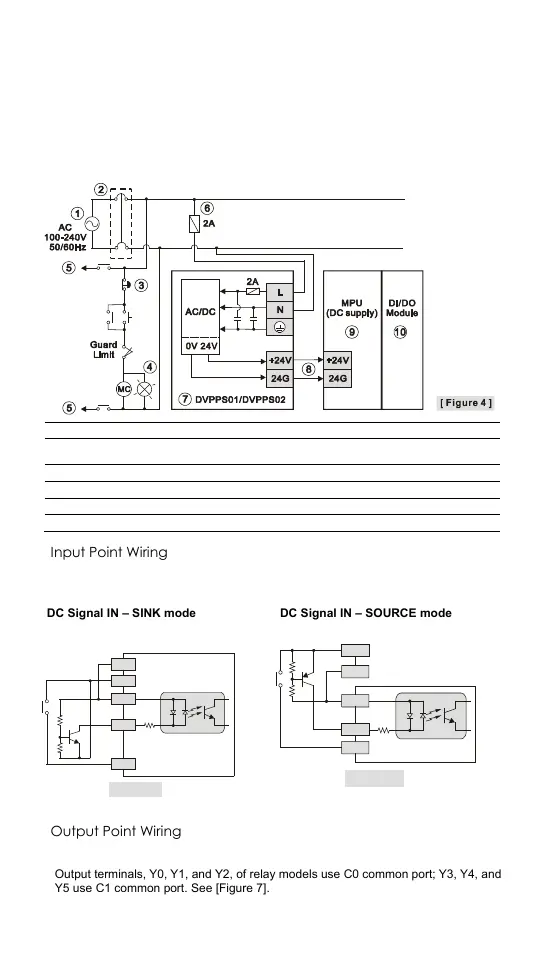
Since DVP-SS2 is only compatible with DC power supply, Delta’s power supply modules
(DVPPS01/DVPPS02) are the suitable power supplies for DVP-SS2. We suggest you
install the protection circuit at the power supply terminal to protect DVPPS01 or
DVPPS02. See the figure below.
AC power supply: 100 ~ 240VAC, 50/60Hz
Emergency stop: This button cuts off the system power supply when accidental
emergency takes place.
Power supply circuit protection fuse (2A)
DC power supply output: 24VDC, 500mA
DVP-PLC (main processing unit)
Input Point Wiring
There are 2 types of DC inputs, SINK and SOURCE. (See the example below. For
detailed point configuration, please refer to the specification of each model.)
DC Signal IN – SINK mode
Input point loop equivalent circuit
DC Signal IN – SOURCE mode
Input point loop equivalent circuit
24G
+24V
S/S
X0
X1
[ Figure 5 ]
+24V
24G
S/S
X0
X1
[ Figure 6 ]
Output Point Wiring
1. DVP-SS2 has two output modules on it, relay and transistor. Be aware of the
connection of shared terminals when wiring output terminals.
2. Output terminals, Y0, Y1, and Y2, of relay models use C0 common port; Y3, Y4, and
Y5 use C1 common port. See [Figure 7]. When the output points are enabled, their
corresponding indicators on the front panel will be on.
 Loading...


