Chapter 4 Communication Setting
LD-E Operation Manual
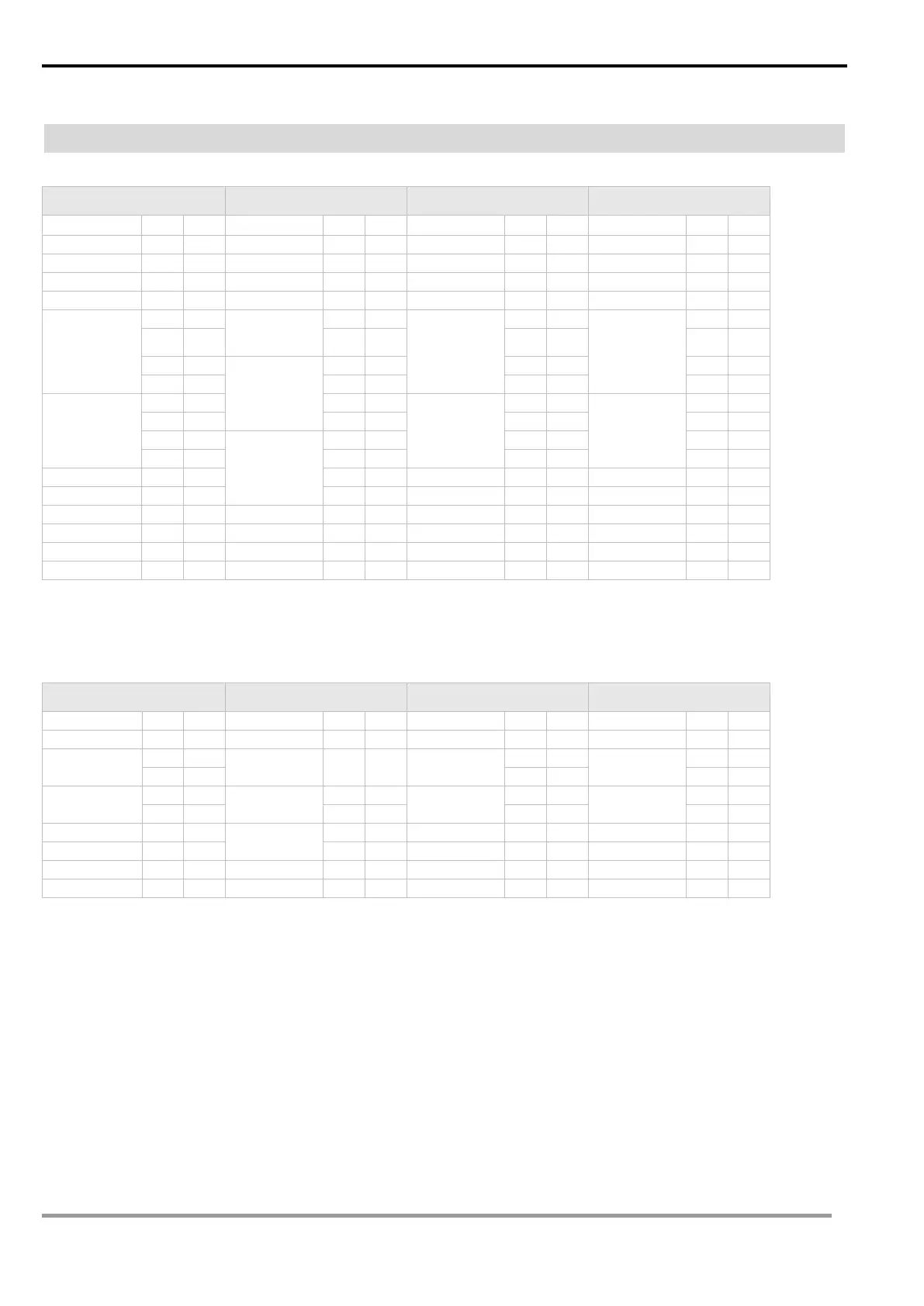
4.2 Communication protocol
ASCII Mode
Read Command
Read Command Response
Write Command Write Command Response
:
:
:
:
Starting data
address
Number of data
Starting data
address
Starting data
address
‘0’ ‘4’ ‘0’ ‘0’
Start address
data
1004H
Number of data
(word/Bit)
Data content
Data content
Address data
1005H
LRC checksum:
LRC check is the added sum from “Address” to “Data content”. For example, 01H + 03H + 10H+ 04H + 00H + 02H = 1AH, then take the
complementary of 2, E6H.
RTU Mode
Read Command
Read Command Response
Write Command Write Command Response
Starting data
address
Number of data
04H
Starting data
Starting data
Number of data
Start address
data 1004H
Data content
Data content
Address
data1005H
CRC (Cyclical Redundancy Check) is obtained by the following steps.
1. Load in a 16-bit register FFFFH as the CRC register.
2. Do an exclusive OR operation of the first byte of the data and low byte of CRC register, and place the operation result back to the CRC register.
3. Right shift the bits in the CRC register and fill the high bits with “0”. Check the removed lowest bit.
4. If the removed lowest bit is “0”, repeat step 3. Otherwise, do an exclusive OR operation of the CRC register and the value A001H and place the
operation result back to the CRC register.
5. Repeat step 3 and 4 until the 8 bits (1 byte) are all right shifted.
6. Repeat step 2 and 5 and calcualte all the bits to obtain CRC check.
Please be aware of the high/low byte transmission order in the CRC register.
 Loading...
