5
VFD-B Series
DELTA ELECTRONICS, INC. ALL RIGHTS RESERVED
5-21
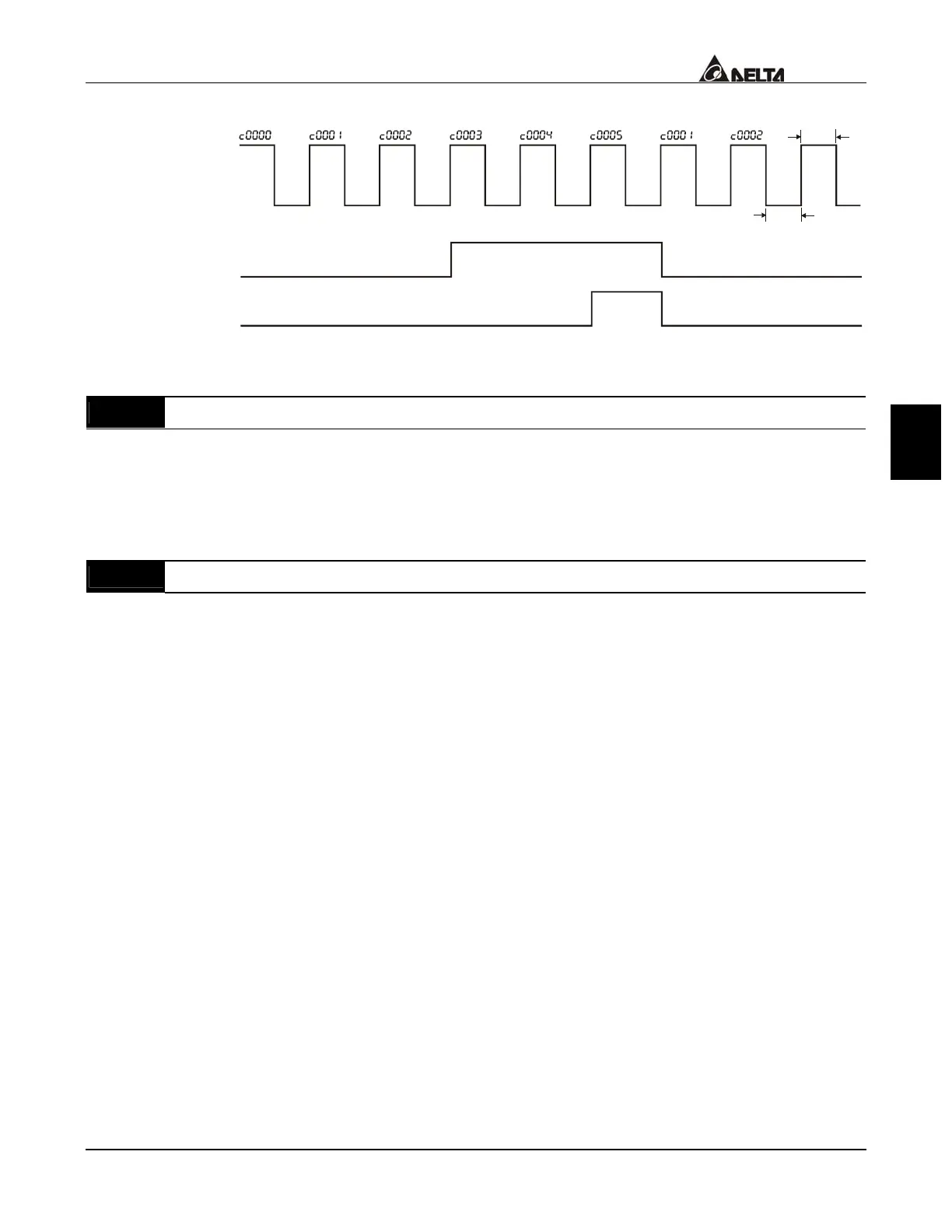
The timing diagram:
Terminal Count Value
(Pr. 03-00~Pr. 03-03=14)
Preliminary Count Value
(Pr. 03-00~Pr. 03-03=15)
Display
(Pr.00-04=01)
TRG
Counter Trigger
The width of trigger signal
should not be less than
2ms(<250 Hz)
2msec
2msec
Ex:03-08=5,03-09=3
03 - 11
EF Active when Preliminary Count Value Attained Factory Setting: 00
Settings 00 No function.
01 Preliminary count value attained, EF active.
If this parameter is set to 01, When the desired value of counter is attained, the AC drive
treat it as a fault, the drive will stop and show the “cEF” message on the display.
03 - 12
Fan Control Factory Setting: 00
Settings 00 Always fan on
01 Power off 1 minute later, fan off
02 Run and fan on, stop and fan off
03 Preliminary temperature attained, Fan start to run
This parameter determines the operation mode of cooling fan.
 Loading...