Chapter 5 Main Circuit TerminalsC2000-HS
5-4
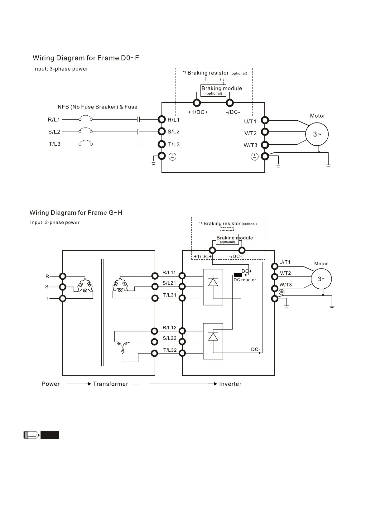
5-1 Main Circuit Diagram
Figure 5-3
*1 Please refer to Chapter 7-1 for more details of brake units.
Figure 5-4
*1 Please refer to Chapter 7-1 for brake units and resistors selection.
NOTE
If the wiring between motor drive and motor is over 75 meters, please refer to Chapter 7-4 Specifications of limits for motor
cable length.
Please remove short circuit plate of Frame G and H if 12 pulse is implemented. Please contact Delta Electronics, Inc. when
using 12 pulse input.
 Loading...
