7
AVR-2310CI/2310/890, AVC-2310
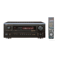
About the photos used for descriptions in the “DISASSEMBLY” section.
• The direction from which the photographs used herein were photographed is indicated at "Direction of photograph: ***" at
the left of the respective photographs.
• Refer to the table below for a description of the direction in which the photos were taken.
• Photographs for which no direction is indicated were taken from above the product.
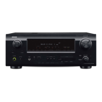
1. PANEL FRONT ASSY
(1) Remove the screws.
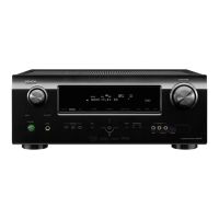
(2) Cut the wire clamp bands, then loose the style pin. Disconnect the connector wire.
The viewpoint of each photograph
(Photografy direction)
[View from above]
Front side
Direction of photograph: B
Direction of photograph: D
Direction of photograph: C
f
Proceeding : CABINET TOP PANEL FRONT ASSY
→
Proceeding : CABINET TOP PANEL FRONT ASSY
→
Direction of photograph: D
Style pin : Loose CP301
cut
cut

 Loading...