9
DVD-1740/558
CABINET DISASSEMBLY INSTRUCTIONS
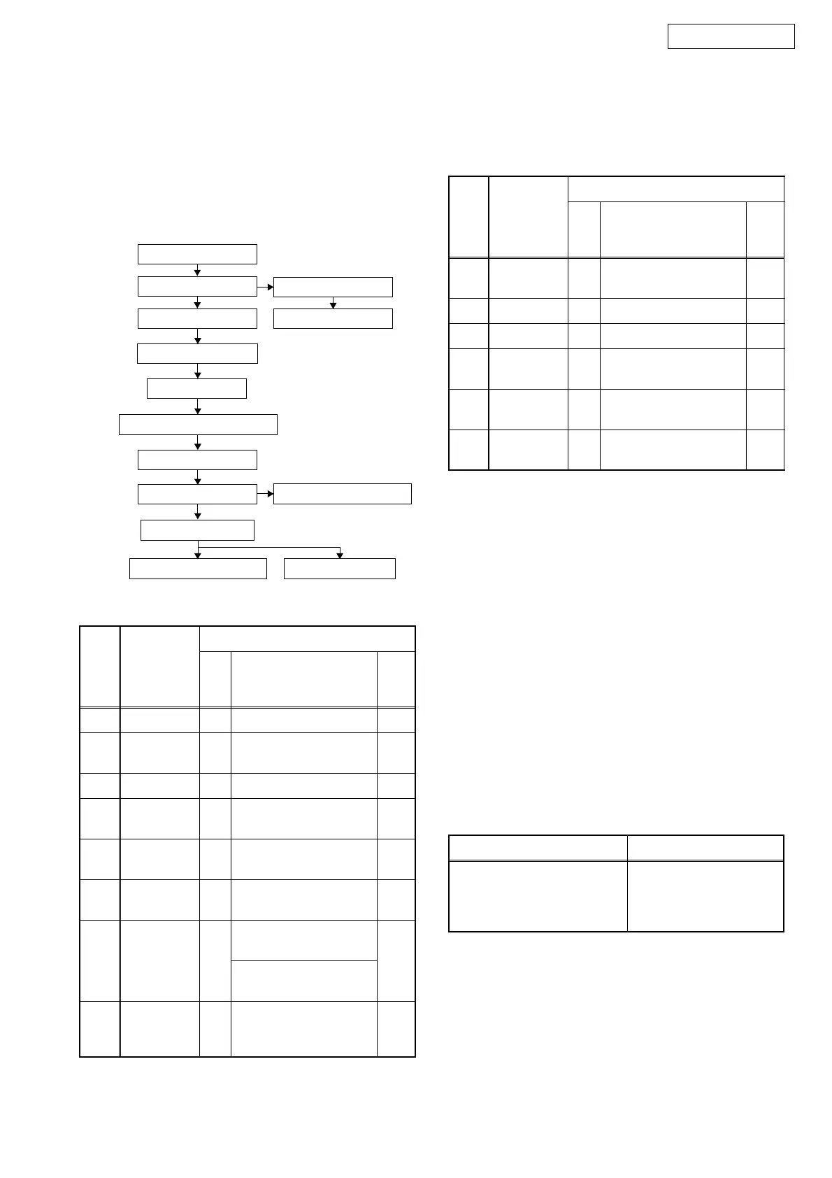
1. Disassembly Flowchart
This flowchart indicates the disassembly steps to gain
access to item(s) to be serviced. When reassembling,
follow the steps in reverse order. Bend, route, and
dress the cables as they were originally.
2. Disassembly Method
Note:
(1) Identification (location) No. of parts in the figures
(2) Name of the part
(3) Figure Number for reference
(4) Identification of parts to be removed, unhooked,
unlocked, released, unplugged, unclamped, or
desoldered.
P = Spring, L = Locking Tab, S = Screw,
CN = Connector
* = Unhook, Unlock, Release, Unplug, or Desolder
e.g. 2(S-2) = two Screws (S-2),
2(L-2) = two Locking Tabs (L-2)
(5) Refer to •Reference Notes.Ž
About tightening screws
When tightening screws, tighten them with the
following torque.
ID/
Loc.
No.
Part
Removal
Fig.
No.
Remove/*Unhook/
Unlock/Release/
Unplug/Desolder
Note
[1] Top Cover D1 5(S-1) ---
[2] Front Unit D2
*4(L-1), *2(L-2),
*3(L-3), *CN2001
1
[3] Tray Panel D2 *2(L-4) 1
[4]
Function
CBA
D3 5(S-2) ---
[5]
Front
Assembly
D3 ---------- ---
[6]
Reinforce
Plate
D4 2(S-3) ---
[7] Rear Panel D4
[DVD1740BKE3]
7(S-4), (S-5), (S-6)
4
[DVD558BKE3]
6(S-4), (S-5), (S-6)
[8]
DVD Main
CBA Unit
D5
(S-7), *CN201,
*CN301, *CN401,
*CN601
2
4
[1] Top Cover
[5] Front Assembly
[2] Front Unit
[3] Tray Panel
[7] Rear Panel
[6] Reinforce Plate
[12] Loader Base
[8] DVD Main CBA Unit
[9] DVD Mechanism
[10] LED CBA
[13] Main PCB Holder
[4] Function CBA
[14] Power PCB Holder
[11] AV CBA
[9]
DVD
Mechanism
D5
D6
4(S-8)
2
3
[10] LED CBA D7 *CN2102 ---
[11] AV CBA D7 4(S-9), (S-10) ---
[12]
Loader
Base
D8 4(S-11) ---
[13]
Main PCB
Holder
D8 (S-12) ---
[14]
Power PCB
Holder
D8 2(S-13) ---
(1)
(2)
(3)
(4)
(5)
Screws Torque
(S-1), (S-2), (S-3), (S-4),
(S-5), (S-6), (S-7), (S-8),
(S-9), (S-10), (S-11),
(S-12), (S-13)
0.45 ± 0.05 N·m
ID/
Loc.
No.
Part
Removal
Fig.
No.
Remove/*Unhook/
Unlock/Release/
Unplug/Desolder
Note
 Loading...