EasyManua.ls Logo

Denon DVD-5000 Service Manual

Denon DVD-5000
64 pages
To Next Page IconTo Next Page
To Previous Page IconTo Previous Page
Page #8 background imageLoading...
Page #8 background image
mga
DVD-5000
(4)
Disconnect
the
cables
connected
between
the
P.W.B.
in
the
front
panel
and
the
Audio
I/F
P.W.B.
(5)
Remove
the
4
screws
@
on
the
top
and
the
4
screws
©
on
the
bottom,
and
remove
the
front
panel
to
the
arrow
direction
shown
in
Figure.
5.
Removing
the
Radiator
(1)
Remove
the
6
screws
©,
and
remove
the
radiator
cover.
(2)
Remove
the
radiator
after
removing
the
4
screws
@.

Other manuals for Denon DVD-5000

Question and Answer IconNeed help?

Do you have a question about the Denon DVD-5000 and is the answer not in the manual?
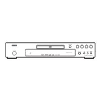
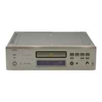
Denon DVD-5000 Specifications

General IconGeneral
BrandDenon
ModelDVD-5000
CategoryDVD Player
LanguageEnglish

Summary

Safety Precautions

Leakage Current Check

Perform before returning the unit to the customer for safety.

Electrostatic Discharge (ESD) Precautions

Traverse Unit Handling

Safe handling procedures for the laser pickup traverse unit.

ESD Prevention Methods

Steps for grounding and preventing static discharge.

Laser Diode Handling

Precautions for laser diode testing and handling.

Servicing Information

Player Initialization Procedures

Procedure to initialize the player after replacing boards.

Loading Base Disassembly/Reassembly

Loading Base Removal

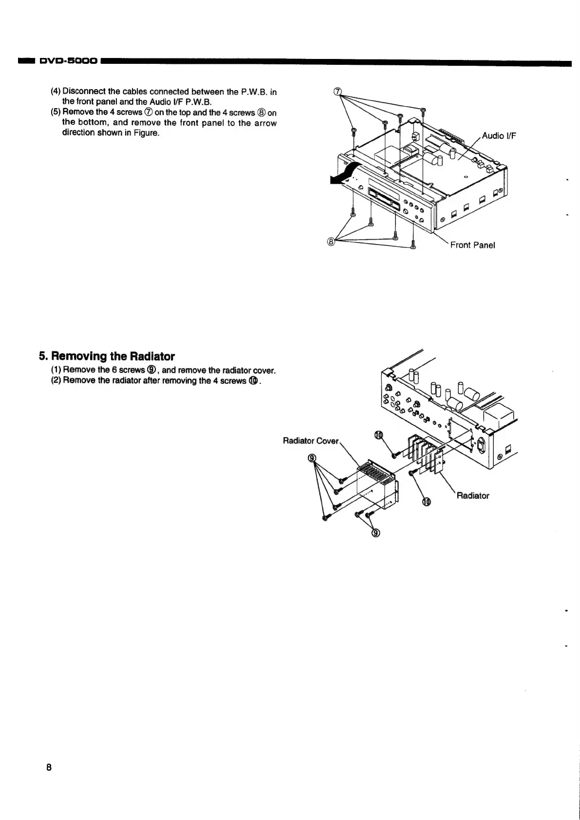
Steps to remove the loading base unit.

Traverse Unit Removal

Steps to remove the traverse unit.

Traverse Unit Assembly

Steps to reassemble the traverse unit.

Traverse Unit Main Parts Replacement

Laser Diode Damage Prevention

Precautions to prevent laser diode damage.

Laser Pick-Up Short-Circuiting

How to short-circuit the laser pick-up for ESD protection.

Parts Replacement Preparation

Steps before replacing parts in the traverse unit.

Laser Pick-Up Replacement

Steps to replace the laser pick-up.

Traverse Motor Unit Replacement

Steps to replace the traverse motor unit.

Disc Motor Replacement

Steps to replace the disc motor.

Adjustment Procedures

Optical Adjustment Points

Details parts needing optical adjustment and general remarks.

Optical Adjustment

Disc Motor Slant Adjustment

Procedure for slant adjustment of the disc motor.

Electrical Adjustment Procedures

Luminance Signal Adjustment

Adjusting the luminance signal output.

Chrominance Signal Adjustment

Adjusting the chrominance signal output.

PB Signal Adjustment

Adjusting the PB signal output.

Fc Correction Procedure

Procedure for Fc correction after replacing FEP IC.

Self-Diagnosis Function

U.H.F. Display Diagnostics

Explains display methods for diagnosis codes.

Semiconductors

DXP6001AF Terminal Function

Pin configuration and function for DXP6001AF IC.

MN1872423 Terminal Function (IC601)

Pinout and function description for IC601.

Printed Wiring Boards

Main PWB Component Side Layout

Component layout diagram for the main PWB.

Main PWB Pattern Side Layout

Solder side layout diagram for the main PWB.

Audio I/F PWB Layout

Component layout for the Audio I/F PWB.

Display PWB Layout

Component layout for the Display PWB.

Related product manuals