MAINTENANCE LAC/LFC Series Oven Owner’s Manual
42 Version 1.12
Copyright © 2018 by Despatch Industries.
All rights reserved. No part of the contents of this manual may be reproduced, copied or transmitted in any form or by any
means including graphic, electronic, or mechanical methods or photocopying, recording, or information storage and
retrieval systems without the written permission of Despatch Industries, unless for purchaser's personal use.
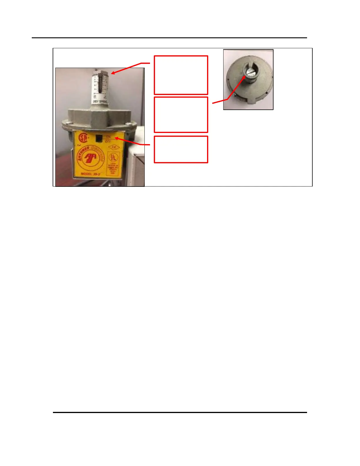
Figure 14. Test Recirculation and Exhaust Airflow Switches.
6.5.1.1. Alternative Method of Checking Power, Switches and Timer
Three LED lights on a circuit board indicate the status of power, airflow switches, and
purge timer. These LEDs serve as indicators if the switches are in the ON/Closed position
when the main oven power is switched ON.
Locate the circuit board behind the front control (Figure 15):
1LED illuminates when the main oven power switch is turned ON
3LED illuminates when all the air flow switch contacts are closed
LED illuminates after the purge timer times out
access
sensitivity
adjustment
adjustment
screw location
shows switch
 Loading...