6
ENGLISH
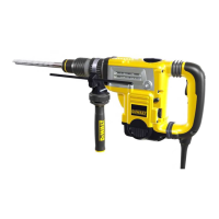
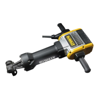
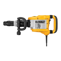
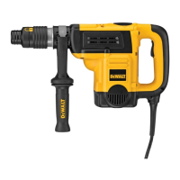
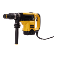
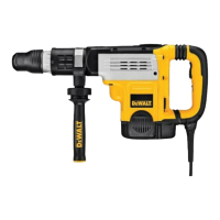
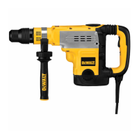
The D25820, D25831 chipping hammers have been designed for
professional chipping, chiselling and demolitionapplications.
DO NOT use under wet conditions or in the presence of flammable liquids
orgases.
These hammers are professional powertools.
DO NOT let children come into contact with thetool. Supervision is
required when inexperienced operators use thistool.
• Young children and theinfirm. This appliance is not intended for use
by young children or infirm persons withoutsupervision.
• This product is not intended for use by persons (including children)
suffering from diminished physical, sensory or mental abilities; lack of
experience, knowledge or skills unless they are supervised by a person
responsible for theirsafety. Children should never be left alone with
thisproduct.
Soft Start Feature
D25601, D25602, D25603, D25831
The soft start feature allows the tool to accelerate slowly, thus preventing
the drill bit from walking off the intended hole position whenstarting.
The soft start feature also reduces the immediate torque reaction
transmitted to the gearing and the operator if the hammer is started with
the drill bit in an existinghole.
Electronic Speed and Impact Control (Fig. A, C)
D25601, D25602, D25603, D25831
The electronic speed and impact control
7
offers the following advantages:
- use of smaller accessories without risk of breakage;
- minimised break-out when chiselling or drilling in soft or brittle
materials;
- optimal tool control for precisechiselling.
Torque Limiting Clutch
WARNING: The user must always maintain a firm grip on the tool
when inoperation.
The torque limiting clutch reduces the maximum torque reaction
transmitted to the operator in case of jamming of a drillbit. This feature also
prevents the gearing and electric motor fromstalling.
NOTICE: Always turn the tool off before changing torque control
settings or damage to tool mayresult.
Complete Torque Control (CTC) (Fig.C) D25602
Complete Torque Control (CTC) offers the user a two-stage mechanical
clutch with adjustable torqueoptions. Adjusting the torque provides
increased control for variousapplications.
The low setting (40Nm) allows the tool to operate at a reduced torque
level increasing control for many solid drillingapplications. The high setting
(80Nm) is available for more demanding applications such as core drilling
and the use of large diameter solidbits.
Refer to Setting the Two Stage Mechanical Clutch for moreinformation.
Ultimate Torque Control (UTC) (Fig.C) D25603
In addition to the two-stage mechanical clutch, Ultimate Torque Control
(UTC) offers increased user comfort and safety through an on-board,
anti-rotation technology capable of detecting if the user loses control
of thehammer. When a jam is detected, the torque and speed are
reducedinstantly. This feature prevents self rotation of the tool reducing the
occurrence of wristinjuries.
Service Indicator LEDs (Fig. A, C)
D25601, D25602, D25603, D25831
The yellow brushwear indicator LED
17
lights up when the carbon brushes
are nearly worn out to indicate that the tool needs servicing within the next
8 hours ofuse.
D25601, D25602, D25603
The red service indicator LED
18
lights up if the lock-on button
2
is
used in any mode except the chippingmode. On models fitted with
Ultimate Torque Control (UTC), the red LED indicator
18
lights up if the
anti-rotational device isactivated. The red indicator starts to flash if there
is a fault with the tool or the brushes have completely worn out (refer to
Brushes under Maintenance).
D25831
The red service indicator LED
18
lights up if there is a fault with the
tool or the brushes have completely worn out (refer to Brushes under
Maintenance).
Fully Vibration-Dampened Main Handle (Fig. A)
D25601, D25602, D25603, D25831
The dampers in the main handle
4
absorb the vibrations transmitted to
theuser. This improves user comfort during theoperation.
ASSEMBLY AND ADJUSTMENTS
WARNING: To reduce the risk of serious personal injury,
turn tool off and disconnect tool from power source before
making any adjustments or removing/installing attachments
oraccessories. Be sure the trigger switch is in the OFFposition. An
accidental start-up can causeinjury.
Assembling and Fitting the Side Handle
(Fig. B)
The side handle
3
can be mounted on either side of the machine to suit
both right- and left-handedusers.
WARNING: Always operate the tool with the side handle
properlyassembled.
D25501, D25601, D25602, D25820, D25603
1. Snap the steel ring
10
over the collar
15
behind the tool holder
12
.
Squeeze both ends together, mount the bush
11
and insert the
pin
14
.
2. Place the side handle clamp
9
and screw on the clamp wheel
8
. Do
nottighten.
WARNING: Once assembled, the side handle clamp should never
beremoved.
3. Screw the side handle
3
into the bush
11
and then into clampwheel.
Tightensecurely.
4. Rotate the side handle mounting assembly to the desiredposition. For
drilling horizontally with a heavy drill bit, we recommend to place the
side handle at an angle of approximately 20° for optimumcontrol.
5. Lock the side handle mounting assembly in place by tightening the
clamp wheel
8
.
D25831
1. Unscrew the side handle knob
16
.
2. Slide the side handle assembly onto the machine locating the steel
ring
10
in the mounting area
26
. The correct position of the side
handle is between head and middle of thetube.
3. Adjust the side handle
3
to the desiredangle.
4. Slide and rotate the side handle to the desiredposition.
5. Lock the side handle in place by tightening the knob
16
.
Inserting and Removing SDS Max® Accessories
(Fig. A, D)
This machine uses SDS Max
®
bits and chisels (refer to the inset in figureDB
for a cross-section of an SDS Max
®
bit shank).
1. Clean the bitshank.
2. Pull back the locking sleeve
13
and insert the bitshank.
3. Turn the bit slightly until the sleeve snaps intoposition.
4. Pull on the bit, to check if it is properlylocked. The hammering function
requires the bit to be able to move axially several centimetres when
locked in the toolholder.
 Loading...