11
ENGLISH
Voltage Amperes Cable rating (Amperes)
230 0 - 2.0 6 6 6 6 6 6
2.1 - 3.4 6 6 6 6 6 6
3.5 - 5.0 6 6 6 6 10 15
5.1 - 7.0 10 10 10 10 15 15
7.1 - 12.0 15 15 15 15 20 20
12.1 - 20.0 20 20 20 20 25 -
Connecting to the mains
The mains supply to be used for this machine must
be equipped with a 16 A cut-out fuse with time delay.
Voltage drops
Inrush currents cause short-time voltage drops.
Under unfavourable power supply conditions, other
equipment may be affected.
If the system impedance of the power supply is lower
than 0.25 Ω, disturbances are unlikely to occur.
Assembly and adjustment
Prior to assembly and adjustment always
unplug the tool.
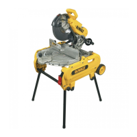
Bench mounting (fig. A)
Mounting holes (9) have been provided to facilitate
bench mounting.
Removing and fitting a cutting disc (fig. B1 - B3)
• With the arm in the rest position, use the lip (15)
to slide the guard (4) back. Leave the guard
retracted (fig. B1).
• Press and hold down the spindle lock (6) (fig. B2).
• Rotate the cutting disc (5) until it locks.
• Using the Allen key (14), remove the bolt (16) by
turning counterclockwise and then remove the flat
washer (17) and the retaining flange (18) (fig. B2).
• Check that the spacer (19) is in place against the
flange (20).
• Replace the cutting disc (5). Make sure that the
new disc is placed onto the spacer (19) in the
correct rotational direction.
• Secure the blade with the retaining flange (18),
the flat washer (17) and the bolt (16).
• Move the guard back down and release the
spindle lock (6).
• Adjust the cutting depth as necessary (fig. B3).
Adjusting the cutting depth (fig. B3)
The cutting depth can be adjusted to meet the wear
of the cutting disc.
• Make a dry run with the tool switched off and
check for clearance.
• If adjustment is required, proceed as follows:
• Loosen the lock nut (21) a few turns.
• Turn the depth stop bolt (12) in or out as to
achieve the required cutting depth.
• Tighten the lock nut (21).
Always adjust the depth stop to its original
position when replacing the cutting disc.
Clamping the workpiece in position
(fig. A & C1 - C4)
The tool is equipped with a material clamp (6) (fig. A).
• Pull the lever (22) toward the handle (23) (fig. C1).
• Push the clamp shaft (24) forward until the jaw
(25) is almost touching the workpiece.
• Press the lever (22) toward the jaw (25) until it
engages with the clamp shaft (24).
• Rotate the handle (23) clockwise and clamp the
workpiece securely.
• To release the workpiece, rotate the handle (23)
counterclockwise.
• To increase the cutting capacity, place a
spacer block (26) under the workpiece
(27). The spacer block should be slightly
narrower than the workpiece (fig. C2).
• Support long workpieces using a piece
of wood (28) (fig. C3). Do not clamp the
cut off end (27).
Quick travel feature (fig. C1)
The clamp has a quick travel feature.
• To release the clamp, rotate the handle (23) one
or two turns counterclockwise and pull the lever
(22) toward the handle (23).
Setting the clamping position (fig. C4)
The clamping position can be set to match the
cutting disc.
• Remove the fence bolts (29) using the Allen key (14).
• Move the fence (8) as required.
• Re-fit the fence bolts (29) and tighten them to
lock the fence (8).
 Loading...