7
ENGLISH
Read instruction manual beforeuse.
Wear earprotection.
Wear eyeprotection.
Borediameter.
Date Code Position (Fig. A)
The date code
18
, which also includes the year of manufacture,
is printed into thehousing.
Example:
2018 XX XX
Year of Manufacture
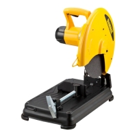
Description (Fig. A, E)
WARNING: Never modify the power tool or any part of it.
Damage or personal injury couldresult.
1
Lock pin
2
Spark deflector screw
3
Spark deflector
4
Base
5
Fence
6
Vise
7
8mm Hex key
8
Crank
9
Vise lever
10
Wheel
11
Guard
12
Spindle lock
13
Fence bolts
14
Trigger switch
15
Padlock hole
16
Mounting holes
17
Operating handle
18
Date code
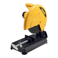
Intended Use
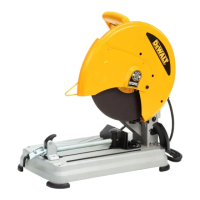
Your D28730 chop saw has been designed for the cutting of
variously shaped steelmaterials.
DO NOT use under wet conditions or in the presence of
flammable liquids orgases.
The D28730 chop saw is a professional powertool.
DO NOT let children come into contact with the tool.
Supervision is required when inexperienced operators use
thistool.
• This product is not intended for use by persons (including
children) suffering from diminished physical, sensory or
mental abilities; lack of experience, knowledge or skills
unless they are supervised by a person responsible for their
safety. Children should never be left alone with thisproduct.
Cutting Capacity
The wide vise opening and high pivot point provide cutting
capacity for many large pieces. Use the cutting capacity chart to
determine total maximum size of cuts that can be made with a
newwheel.
CAUTION: CERTAIN LARGE, CIRCULAR OR
IRREGULARLY SHAPED OBJECTS MAY REQUIRE
ADDITIONAL HOLDING MEANS IF THEY CANNOT BE
HELD SECURELY INVISE.
CAUTION: DO NOT CUT MAGNESIUM WITH
THISTOOL.
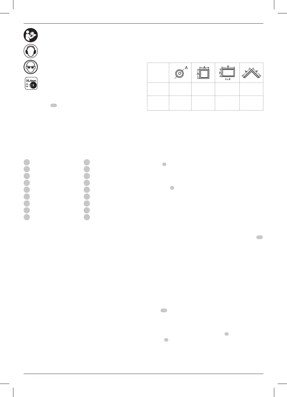
Maximum Cutting Capacity
NOTE: Capacity shown on chart assumes no wheel wear and
optimum fenceposition.
Workpiece
Shape
90° Cutting angle A = 130 mm A = 120 mm 115 mm x 130 mm A = 135 mm
45° Cutting angle A = 115 mm A = 102 mm 110 mm x 102 mm A = 110 mm
OPERATION
Instructions for Use
WARNING: Always observe the safety instructions and
applicableregulations.
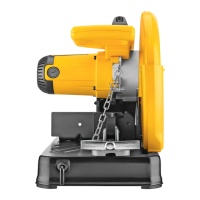
To Carry (Fig. A)
Fold down unit to position where you can carry the saw. Push in
lock pin
1
to lock armdown.
Unlocking (Fig. A)
To unlock tool and raise head, depress motor arm slightly and
pull lock pin
1
out. Motor arm will then pivotupward.
Mounting (Fig. D, F)
CAUTION: Tool must be supported on stable, level,
non-skid surface to prevent unexpected movement
whenoperating.
1. Drill holes through the work surface that align the base of
the chopsaw.
2. Insert two M10 bolts down through the mounting holes
16
in the base and through holes in mounting surface. The
approximate length of the screws should be the thickness of
the mounting surface plus 102mm.
Proper Hand Position (Fig. A)
WARNING: To reduce the risk of serious personal injury,
ALWAYS use proper hand position as shown.
WARNING: To reduce the risk of serious personal
injury, ALWAYS hold securely in anticipation of a
suddenreaction.
Proper hand position requires one hand on the operating
handle
17
, with the other hand guiding theworkpiece.
Spark Deflector Adjustment (Fig. A)
To best deflect sparks away from surrounding persons and
materials, loosen the spark deflector screw
2
, adjust the spark
deflector
3
and then retighten screw. Do not allow cordset to
come into contact with deflector or sparks as damage to cordset
mayoccur.
 Loading...