11
ENGLISH
ASSEMBLY
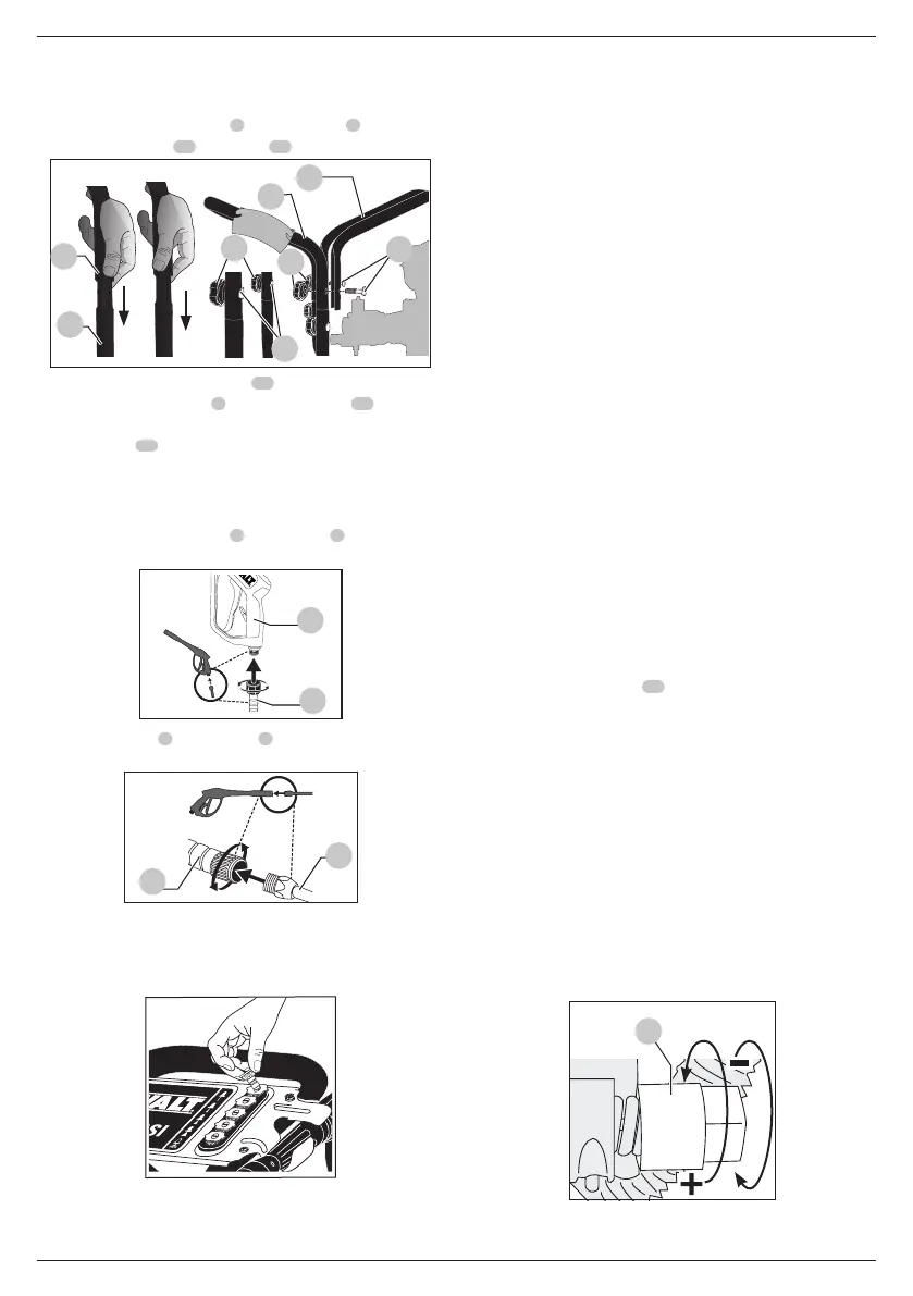
Pressure Washer Assembly (Fig.B, C–F)
1. Slide the handle assembly
8
onto the frame
6
and secure
with saddle bolts
20
andknobs
21
.
Fig. C
8
6
20
21
22
20
21
8
2. Align holes in the top handle
22
with the mounting holes
in the handle assembly
8
. Insert saddle bolts
20
through
aligned holes and secure top handle to handle assembly
with knobs
21
. Tighten untilsnug.
CAUTION: Risk of personal injury. Avoid placing
hands between handle and frame when assembling to
preventpinching.
3. Attach high pressure hose
9
to spray gun
3
. Make sure it
issecure.
Fig. D
9
3
4. Connect wand
5
to spray gun
3
. Make sure connection
issecure.
Fig. E
5
3
5. Remove the five coloured quick-connect nozzles from the
plastic bag and insert them into correct grommet on the
nozzle holder. Nozzles are colour coded to match coloured
nozzles on panelassembly.
Fig. F
6. Check the tyre pressure and add air if needed.
NOTE:Air tanks, compressors and similar equipment used
to inflate tyres can fill small tyres similar to these very rapidly.
Adjust pressure regulator on air supply to no more than the
rating of the tyre pressure. Add air in small increments and
frequently use the tyre gauge to prevent overinflation.
WARNING: Risk of bursting. Use a tyre pressure gauge
to check the tyres pressure before each use and while
inflating tyres; see the tyre sidewall for the correct
tyrepressure.
OPERATION
Instructions for Use
WARNING: Always observe the safety instructions and
applicableregulations.
WARNING: Use only DeWALT battery packs andchargers.
Pressure Adjustments
The pressure setting is preset at the factory to achieve
optimum pressure and cleaning. To lower the pressure, follow
theseinstructions.
1. Back away from the surface to be cleaned. The further away
the nozzle is, the less the pressure will be on the surface to
becleaned.
2. Change to the 40˚ nozzle (white). This nozzle delivers a less
powerful stream of water and a wider spray pattern. Refer to
Spray WandNozzles.
3. This pressure washer's high pressure pump is equipped with
an adjustable unloader
30
(Fig. G) feature that allows the
pressure setting to be adjusted. To lower the pressure, turn
the pressure control knob on the pump counterclockwise
to the desired pressure. To return the pump pressure to the
factory setting, turn the pressure control knob on the pump
clockwise until itstops.
NOTICE: DO NOT try to turn pressure regulator knob past
the built-in stop or damage to the pump willresult.
NOTICE: DO NOT overtighten the pressure control knob.
If overtightened the knob COULD break and result in
immediate loss of water pressure and costly repairs to
theunit.
NOTICE: DO NOT attempt to increase pump pressure. A
higher pressure setting than the factory set pressure may
damage thepump.
Fig. G
30
 Loading...