ENGLISH
14
Three Year Limited Warranty
will repair or replace, without charge, any defects
due to faulty materials or workmanship for three years
from the date of purchase (two years for batteries). This
warranty does not cover part failure due to normal wear
or tool abuse. For further detail of warranty coverage and
warranty repair information, visit www.dewalt.com or
call 1-800-4-
(1-800-433-9258). This warranty does
not apply to accessories or damage caused where repairs
have been made or attempted by others. THIS LIMITED
WARRANTY IS GIVEN IN LIEU OF ALL OTHERS, INCLUDING
THE IMPLIED WARRANTY OF MERCHANTABILITY AND
FITNESS FOR A PARTICULAR PURPOSE, AND EXCLUDES
Register Online
Thank you for your purchase. Register your product nowfor:
• WARRANTY SERVICE: Registering your product will
help you obtain more efficient warranty service in case
there is a problem with yourproduct.
• CONFIRMATION OF OWNERSHIP: In case of an
insurance loss, such as fire, flood or theft, your
registration of ownership will serve as your proof
ofpurchase.
• FOR YOUR SAFETY: Registering your product will
allow us to contact you in the unlikely event a safety
notification is required under the Federal Consumer
SafetyAct.
• Register online at www.dewalt.com
Repairs
The charger and battery pack are notserviceable. There are
no serviceable parts inside the charger or battery pack.
WARNING: To assure product SAFETY and
RELIABILITY, repairs, maintenance and adjustment
(including brush inspection and replacement, when
applicable) should be performed by a
factory
service center or a
authorized service center.
Always use identical replacementparts.
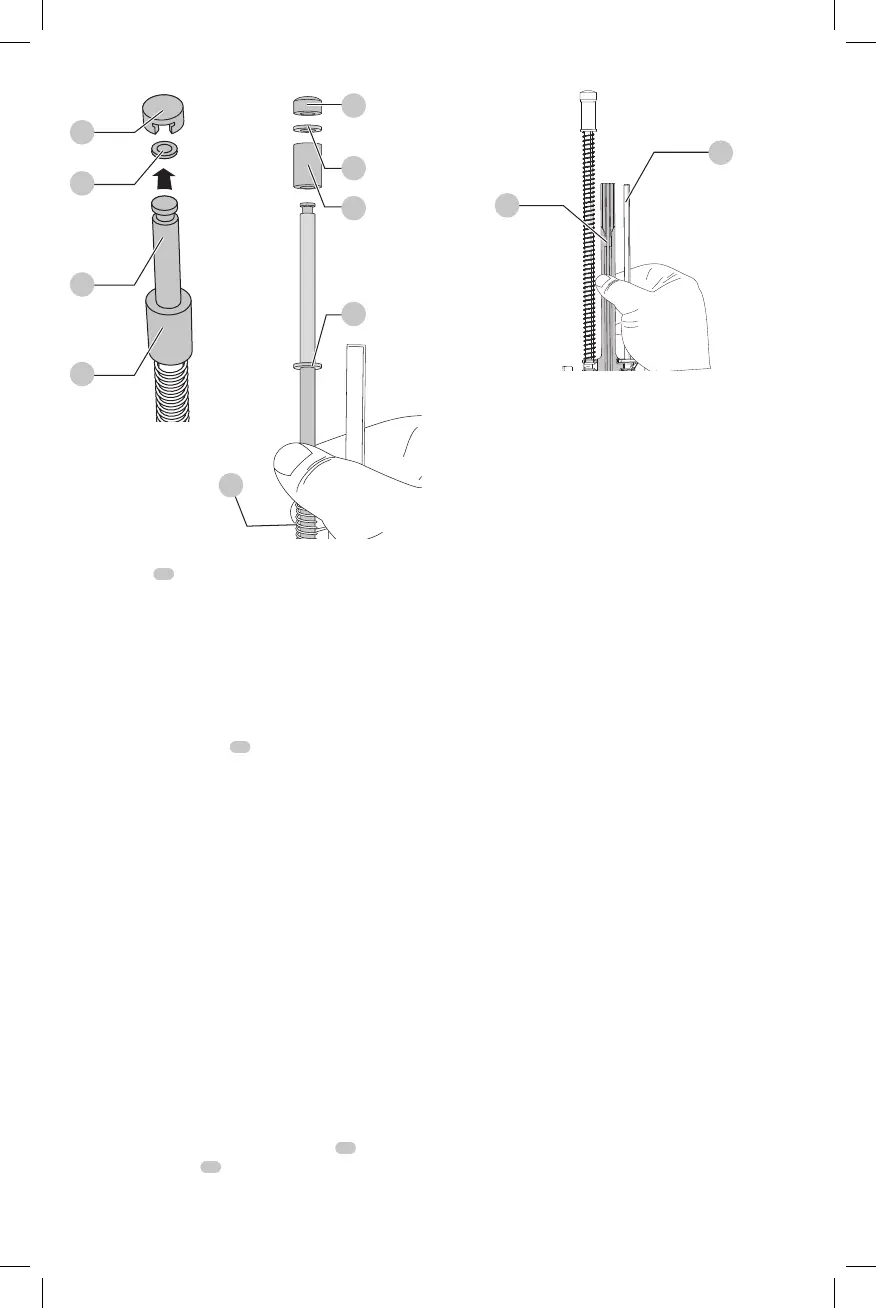
Fig. L
17
18
19
Fig. M
19
20
20
20
21
17
5. Mount the new return spring and washer on to the
spring rail
18
. While compressing the spring with the
washer near the opposite end of the rail, twist on the
new spring bumper until it is past the groove for the
spring railclip.
6. Mount the new spring rail clip securely and position the
bumper against theclip.
NOTE: Check the return of the profile by sliding the
profile up the spring rail and letting it go. It should
return due to the force from thesprings.
7. Slide the return system
16
back into the unit. Check
proper installation by connecting a battery and pushing
then releasing the nose of the unit against a bench or
hard surface. This will start the motorspinning.
NOTE: When the profile and the flywheel are correctly
aligned, you will hear the motor coast back down
from full speed. If the profile and the flywheel are not
correctly aligned, the motor may not start up or may
slow down much faster than normal along with a loud
grinding noise from the unit. If this happens remove
battery, then remove and reseat the returnsystem.
WARNING: Always test the unit by firing short nails
in to soft wood, to ensure that the tool is working
properly. If tool does not operate properly, contact a
recognized
service centerimmediately.
Replacing the Profile (Fig. N)
To Change a Broken or Worn Profile
1. Refer to Return Spring Replacement Steps 1–4 to
remove the return system from the unit and to remove
thespring.
2. Take note of the orientation of the profile
22
. Slide the
profile off therails
18
Fig. N
22
18
3. In the same orientation as the old profile, slide the new
profile onto therails.
4. Refer to Return Spring Replacement Steps 5–7 to
complete theservice.
 Loading...