12
ENGLISH
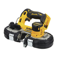
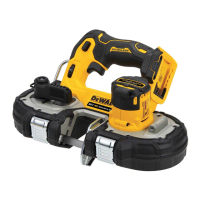
Inserting and Removing the Battery Pack
from the Tool (Fig. B)
NOTE: Make sure your battery pack
14
is fullycharged.
To Install the Battery Pack into the Tool Handle
1. Align the battery pack
14
with the rails inside the tool’s
handle (Fig. B).
2. Slide it into the handle until the battery pack is firmly seated
in the tool and ensure that you hear the lock snap intoplace.
To Remove the Battery Pack from the Tool
1. Press the release button
15
and firmly pull the battery pack
out of the toolhandle.
2. Insert battery pack into the charger as described in the
charger section of thismanual.
Fuel Gauge Battery Packs (Fig.B)
Some DEWALT battery packs include a fuel gauge which
consists of three green LED lights that indicate the level of
charge remaining in the batterypack.
OPERATION
Instructions for Use
WARNING: Always observe the safety instructions and
applicableregulations.
WARNING: To reduce the risk of serious personal
injury, turn tool off and disconnect battery pack
before making any adjustments or removing/
installing attachments or accessories. An accidental
start‑up can causeinjury.
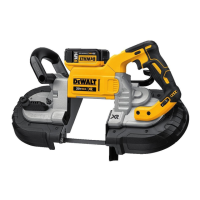
LED Worklight (Fig. A)
CAUTION: Do not stare into worklight. Serious eye
injury couldresult.
There is a worklight
17
located above the blade The worklight
is activated when the trigger switch is depressed, and will
automatically turn off 20seconds after the trigger switch is
released. If the trigger switch remains depressed, the worklight
will remainon.
NOTE: The worklight is for lighting the immediate work surface
and is not intended to be used as aflashlight.
Variable Speed Control (Fig. G)
A speed control wheel
3
is located near the trigger of the
saw. The speed increases as the wheel is turned from a low
speed setting of 1(150m/min) to a high speed setting
of5(380m/min).
The further the trigger is depressed the higher the speed of
thesaw.Releasing the trigger switch turns the motor OFF.
Releasing the trigger switch also automatically actuates
lock-offbutton.
WARNING: This tool has no provision to lock the switch
in the ON position, and should never be locked ON by any
othermeans.
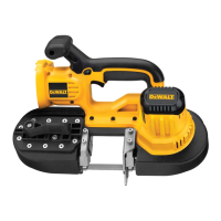
Variable Speed Trigger Switch (Fig. A, G)
Release switch lock‑off button
1
by pressing button. Pull the
variable speed trigger switch
2
to turn the motor ON. The
variable speed trigger switch will give you added versatility.
Blade Selection
In general, first consider the size and shape of the work, and
the type of material to be cut. Remember, for the most efficient
cutting, the coarsest tooth blade possible should be used in
a given application, because the coarser the tooth, the faster
the cut. In selecting the appropriate number of teeth per inch
of the band saw blade, at least two teeth should contact the
work surface when the blade is rested against the workpiece.
As a rule of thumb, soft materials usually require coarse
tooth blades, while hard materials require fine tooth blades.
Where a smoother finish is important, select one of the finer
toothblades.
Select the appropriate band saw blade according to the material
type, dimensions, and number of teeth. See Bi‑Metal Band Saw
Blade Descriptionchart.
The following table is intended as a general guide only.
Determine the type of material and dimension of the workpiece
and select the most appropriate band sawblade.
NOTICE: Never use the band saw to cut resin materials
which are subject to melting. Melting of resin material
caused by high heat generated during cutting may cause
the band saw blade to become bound to the material,
possibly resulting in overload and burn‑out of themotor.
BI-METAL BAND SAW BLADE DESCRIPTION
Number of Teeth
Workpiece Thickness 24 18 14 14/18
3.2 mm and under
3.2–6.4 mm
Blades
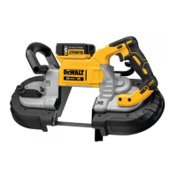
This portable band saw is setup for use with .0.5 mm thick,
12.7mm wide and 686mm–692mm long blades. DO NOT use
0.64mm thickblades.
WARNING: The use of any other blade or accessory might
be hazardous. DO NOT use any other type of accessory
with your band saw. Blades used on stationary band saws
are of different thickness. Do not attempt to use them on
your portableunit.
2. Use a 10mm wrench to loosen the locking nut
7
(Fig.F).
3. Use a 3mm hex wrench
5
to turn the tracking screw
13
1/4 turn clockwise or counterclockwise (Fig.F).
NOTE: Turning the tracking screw clockwise(+) moves
the blade toward the guide roller, turning the tracking
screw counterclockwise(‑) moves the blade away from the
guideroller.
4. Tighten the locking nut and close the blade tension lever
and blade guard. (It will be necessary to run the saw to
observe the tracking.)
5. Observe blade tracking between runs and repeat Steps 1–4
as necessary to achieve proper bladetracking.
 Loading...