ENGLISH
12
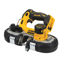
DeWALT Bluetooth® Tool Tag Ready (Fig. A)
Optional Accessory
WARNING: Read instruction manual for the DeWALT
Bluetooth® ToolTag.
WARNING: Remove battery from tool before installing
the DeWALT Bluetooth® ToolTag.
WARNING: When installing or replacing the DeWALT
Bluetooth® Tool Tag, use only the screws provided. Be
sure to securely tighten thescrews.
Your tool comes with mounting holes
15
and fasteners
27
for installing a DeWALT Bluetooth® Tool Tag (DCE041). You
will need a T15 torx bit tip to install the tag. Screw torque
should be between 0.8 and 1.2 Nm (7.1 to 10.6 in‑lbs). The
DeWALT Tool Tag is designed for tracking and locating
professional power tools, equipment, and machines using
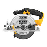
Adjusting the Guard Angle (Fig. E)
WARNING: Do not use guard rotation handle to
hold tool while cutting. Guard rotation handle is
only used for adjustment of the guard while tool is not
inuse.
CAUTION: Guard may be hot. Use guard handle to
rotateguard.
WARNING: Always make sure the guard is properly
engaged before starting themachine.
You can adjust the angle of theguard.
1. To adjust the angle of the guard, pull back the guard
rotation release lever
14
and holdit.
2. Grasp the guard
9
firmly by guard rotation handle
10
and rotate to desiredangle.
3. Release the guard rotation release lever and make sure it
engages, locking the guard in place. If the guard rotation
release lever doesn't engage, rotate the guard slightly
until the guard rotation release lever returns to the
lockedposition.
Replacing Worn Clamp Washers (Fig. D)
WARNING: Replace clamp washers as they wear. They
may become sharp with extendeduse.
1. Remove the arbor screw
11
, outer clamp washer
21
and used wheel
22
if one is installed as described in
Installing Abrasive and DiamondWheels.
2. To remove the inner clamp washer
23
, first remove the
retainingring that holds the inner clamp washer to the
double Dshaft.
3. Remove the inner clamp washer and replace with a new
one. Orient the inner clamp washer with the depressed
center section toward the blade. Make sure the new
inner clamp washer is secure with the retaining ring
inplace.
4. Install the wheel
22
, new outer clamp washer
21
, and
arbor screw
11
as described in Installing Abrasive and
DiamondWheels.
CAUTION: Only use 9" (230mm) Type 1/41 wheels
with 7/8" (22.2mm) arbor hole with this tool. Never
force a wheel onto the machine or alter the size of the
arborhole.
Installing Abrasive and Diamond Wheels
(Fig. A, D)
WARNING: Install only oneblade.
1. Lay unit on a firm surface, with the arbor screw
11
facingupward.
2. Using supplied 1/2" (13mm) open end wrench
6
(located in the battery compartment), remove arbor
screw
11
, outer clamp washer
21
and used wheel
22
if one is installed. Hold arbor screw
11
from turning with
spindle lock button
13
. Spindle threads are righthand.
3. The inner clamp washer
23
is held in place with a
double D shaft and retainingring.
4. Slip wheel over spindle
25
. Slip on outer clamp washer.
Start threading on arbor screw which will self align outer
clampwasher.
IMPORTANT: Make sure the diamond blade is installed
with the correct rotation, as marked on the blade rotation
indicator
12
.
5. Engage spindle lock button and tighten screw firmly with
wrench. Do not over‑tighten arborscrew.
6. Turn wheel by hand to ensure it is properly centered. The
wheel should not hit the shoe or guard. The screw and
flanges should betight.
Spindle Lock Button (Fig. A)
The spindle lock button
13
is used to lock the arbor
screw
11
when changingaccessories.
1. To engage the spindle lock button, remove the battery
pack and make sure trigger switch is in the OFF position
and lock‑off button isengaged.
2. Depress the spindle lock button and turn the wheel and
spindle until the lock button engages thespindle.
3. Use supplied wrench
6
to unscrew the arbor screw
11
and remove or mount accessories. Spindle threads are
righthand.
Lock‑Off Button (Fig. A)
Your cut‑off tool is equipped with a lock‑off button
3
.
To lock the trigger switch in the OFF postition, push the
lock‑off button from the left side of the tool. To unlock the
trigger switch, push the lock‑off button from the right side
of thetool.
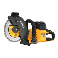
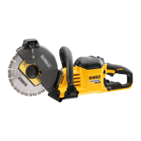
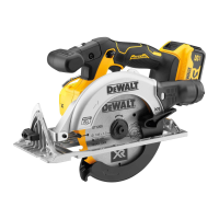
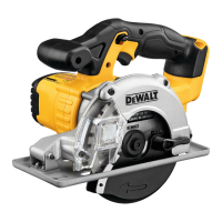
SPECIFICATIONS
DCS692
Blade diameter 9" (230 mm)
Arbor size 7/8" (22.2 mm)
RPM 6600
ASSEMBLY AND ADJUSTMENTS
WARNING: To reduce the risk of serious personal
injury, turn unit off and remove the battery pack
before making any adjustments or removing/
installing attachments or accessories. An
accidental start‑up can causeinjury.
 Loading...