12
ENGLISH
Keep hands away fromblade.
Keep hands 100mm from either side of sawblade.
Do not stare directly into the lightsource.
Carryingpoint.
Date Code Position (Fig.C)
The Date Code
64
, which also includes the year of manufacture, is printed into thehousing.
2022XX XX
Year of Manufacture
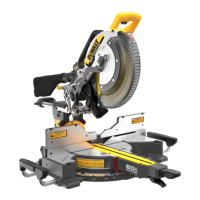
Description (Fig. A)
WARNING: Never modify the power tool or any part of it. Damage or personal injury
couldresult.
1
Trigger switch
2
Operating handle
3
Battery
4
Battery release button
5
Mounting holes
6
Lower guard
7
Mitre lock handle
8
Mitre detent latch
9
Mitre scale
10
Mitre scale screws
11
Hand indentations
12
Fence
13
Bevel lock knob
14
Stabalizer
15
Lifting handle
16
Fence adjustment knob
17
Dust port
18
Table
19
Head lock knob
20
Base
21
XPS On switch
22
Wing nut
23
Vertical material clamp
24
Rails
25
Depth stop
26
Kerf plate
27
Mitre pointer screw
28
0° bevel stop
29
Depth adjustment screw
30
Rail lock knob
31
Mitre scale pointer
32
Extension
Intended Use
Your DeWALT cordless compact mitre saw has been designed for professional cutting wood,
wood products and plastics. When using the appropriate saw blades, sawing aluminum is
also possible. It performs the sawing operations of cross‑cutting, bevelling and mitring easily,
accurately andsafely.
This unit is designed for use with a nominal blade diameter 305mm carbide tipblade.
DO NOT use under wet conditions or in presence of flammable liquids orgases.
These mitre saws are professional powertools.
DO NOT let children come into contact with the tool. Supervision is required when
inexperienced operators use thistool.
WARNING! Do not use the machine for purposes other thanintended.
• Young children and the infirm. This appliance is not intended for use by young children
or infirm persons without supervision.
• This product is not intended for use by persons (including children) suffering from
diminished physical, sensory or mental abilities; lack of experience, knowledge or skills
unless they are supervised by a person responsible for their safety. Children should never
be left alone with thisproduct.
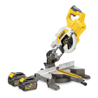
Familiarization (Fig. A, D)
Your mitre saw is not fully assembled in the carton. Refer to Assembling the Base Extensions
and Assembling the Stabilizer Bar sections for assembly instructions. Open the box and lift
the saw out by the convenient lifting handle
15
, as shown in FigureD.
Place the saw on a smooth, flat surface such as a workbench or strongtable.
Examine Figure A to become familiar with the saw and its various parts. The section on
adjustments will refer to these terms and you must know what and where the partsare.
CAUTION: Pinch Hazard. To reduce the risk of injury, keep thumb underneath the handle
when pulling the handle down. The lower guard will move up as the handle is pulled
down which could cause pinching.The handle is placed close to the guard for specialcuts.
Press down lightly on the operating handle
2
and pull the head lock knob
19
and rotate
90degrees. Gently release the downward pressure and hold the arm allowing it to rise to its
full height. Use the head lock knob when carrying the saw from one place to another. Always
use the lifting handle
15
to transport the saw or the hand indentations
11
shown in FigureA.
Use of CUTLINE™ LED Worklight (Fig. A)
CAUTION: Do not stare into worklight. Serious eye injury couldresult.
NOTE: The battery must be charged and connected to the mitresaw.
The CUTLINE™ LED Worklight can be turned on by the momentary switch
21
. The light will
automatically turn off within 20seconds if the saw is not in use. The light is also activated
automatically every time the tool's main trigger
1
ispulled.
To cut through an existing pencil line on a piece of wood, turn on the CUTLINE™ worklight
using the momentary switch
21
(not with the main trigger), then pull down on the operating
handle
2
to bring the saw blade close to the wood. The shadow of the blade will appear
on the wood. This shadow line represents the material that the blade will remove when
performing a cut. To correctly locate your cut to the pencil line, align the pencil line with the
edge of the blade’s shadow. Keep in mind that you may have to adjust the mitre or bevel
angles in order to match the pencil lineexactly.
Your saw is equipped with a battery monitoring feature. The CUTLINE™ worklight begins
to flash when the battery is near the end of its useful charge and/or when the battery is
too hot. Charge the battery prior to continuing cutting applications. Refer to Charging
Procedure under Important Safety Instructions for All Battery Chargers for battery
charginginstructions.
Mitre Control (Fig. A)
The mitre lock lever and mitre detent latch allow you to mitre your saw to 60° right and
50° left. To mitre the saw, lift the mitre lock lever
7
, squeeze the mitre detent latch
8
and
move the mitre arm to the angle desired on the mitre scale
9
as shown at the mitre scale
pointer
31
. Push down on the mitre lock lever to lock the mitre arm inplace.
ASSEMBLY AND ADJUSTMENTS
WARNING: To reduce the risk of serious personal injury, turn machine off and
disconnect battery pack before making any adjustments or removing/installing
attachments or accessories. An accidental start‑up can causeinjury.
WARNING: Use only DeWALT battery packs andchargers.
Assembling the Base Extensions (Fig. E)
WARNING: Base extensions must be assembled to both sides of the saw's base before
using thesaw.
1. The extension
32
should be oriented as shown in Figure E, sliding fully into the U‑shaped
supports. Do not use the saw without mounted extensions!
2. Clamp the extension’s rods against the mitre saw base by inserting the extension
screw
63
entirely through and the clamp.
3. Repeat steps 1and 2on the otherside.
Bench Mounting (Fig. A)
Mounting holes
5
are provided in all 4feet to facilitate bench mounting, as shown in
FigureA. (Two different‑sized holes are provided to accommodate different sizes of screws.
Use either hole, it is not necessary to use both.) Always mount your saw firmly to a stable
surface to prevent movement. To enhance the tool’s portability, it can be mounted to a piece
of 12.7 mm or thicker plywood which can then be clamped to your work support or moved to
other job sites andreclamped.
NOTE: If you elect to mount your saw to a piece of plywood, make sure that the mounting
screws don’t protrude from the bottom of the wood. The plywood must sit flush on the work
support. When clamping the saw to any work surface, clamp only on the clamping bosses
where the mounting screw holes are located. Clamping at any other point will surely interfere
with the proper operation of thesaw.
CAUTION: To prevent binding and inaccuracy, be sure the mounting surface is not
warped or otherwise uneven. If the saw rocks on the surface place a thin piece of material
under one saw foot until the saw sits firmly on the mountingsurface.
Assembling the Stabilizer Bar (Fig. F)
Your saw includes one base stabilizer
14
This must be installed before using your saw. Insert
the stabilizer into the holes in the back of the unit. Move the stabilizer in or out until it contacts
the work surface. Then tighten the screws
62
in the base to fasten thestabilizer.
Changing or Installing a New Saw Blade (Fig. A, G)
WARNING: To reduce the risk of serious personal injury, turn tool off, remove the
battery pack, and place lock lever in the transport position before transporting,
making any adjustments, cleaning, repairing, or removing/installing
attachments or accessories. An accidental start‑up can causeinjury.
WARNING: To reduce the risk of injury, wear gloves when handling the sawblade.
CAUTION:
• Never depress the spindle lock button while the blade is under power orcoasting.
• Do not cut ferrous metal (containing iron or steel) or masonry or fiber cement product
with this mitresaw.
WARNING! Be aware the saw blade shall be replaced in the described way only. Only use
saw blades as specified in section OptionalAccessories.
Removing the Blade (Fig.A, G)
1. Remove battery pack
3
from thesaw.
2. Raise the arm to the upper position and raise the lower guard
6
as far aspossible.
3. Depress the spindle lock button
36
while carefully rotating the saw blade by hand until
the lockengages.
4. Using your finger, pivot the blade bolt plate
38
to gain access to blade bolt head
40
.
5. Keeping the spindle lock button depressed and blade bolt plate pushed out of the way,
use the blade wrench
37
provided to loosen blade screw. (Turn clockwise, left‑hand
threads.) Remove the blade screw.
6. Proceed to remove the outer clamp washer, blade adaptor and sawblade.
 Loading...