ENGLISH
7
b. Check to see if receptacle is connected to a light
switch which turns power off when you turn out
thelights;
c. Move the charger and battery pack to a location
where the surrounding air temperature is
approximately 65°F – 75°F (18° – 24°C);
d. If charging problems persist, take the tool, battery
pack and charger to your local servicecenter.
4. The battery pack should be recharged when it fails to
produce sufficient power on jobs which were easily
done previously. DO NOT CONTINUE to use under these
conditions. Follow the charging procedure. You may also
charge a partially used pack whenever you desire with
no adverse effect on the batterypack.
5. Foreign materials of a conductive nature such as, but
not limited to, grinding dust, metal chips, steel wool,
aluminum foil, or any buildup of metallic particles
should be kept away from charger cavities. Always
unplug the charger from the power supply when there
is no battery pack in the cavity. Unplug the charger
before attempting toclean.
6. Do not freeze or immerse the charger in water or any
otherliquid.
Storage Recommendations
1. The best storage place is one that is cool and dry, away
from direct sunlight and excess heat orcold.
2. For long storage, it is recommended to store a fully
charged battery pack in a cool dry place out of the
charger for optimalresults.
NOTE: Battery packs should not be stored completely
depleted of charge. The battery pack will need to be
recharged beforeuse.
SAVE THESE INSTRUCTIONS FOR
FUTURE USE
Intended Use
This string trimmer is designed for professional trimming
applications. This product is not an edger and is not
intended to be used foredging.
DO NOT use under wet conditions or in presence of
flammable liquids orgases.
This string trimmer is a professional appliance. DO NOT
let children come into contact with the tool. Supervision is
required when inexperienced operators use thistool.
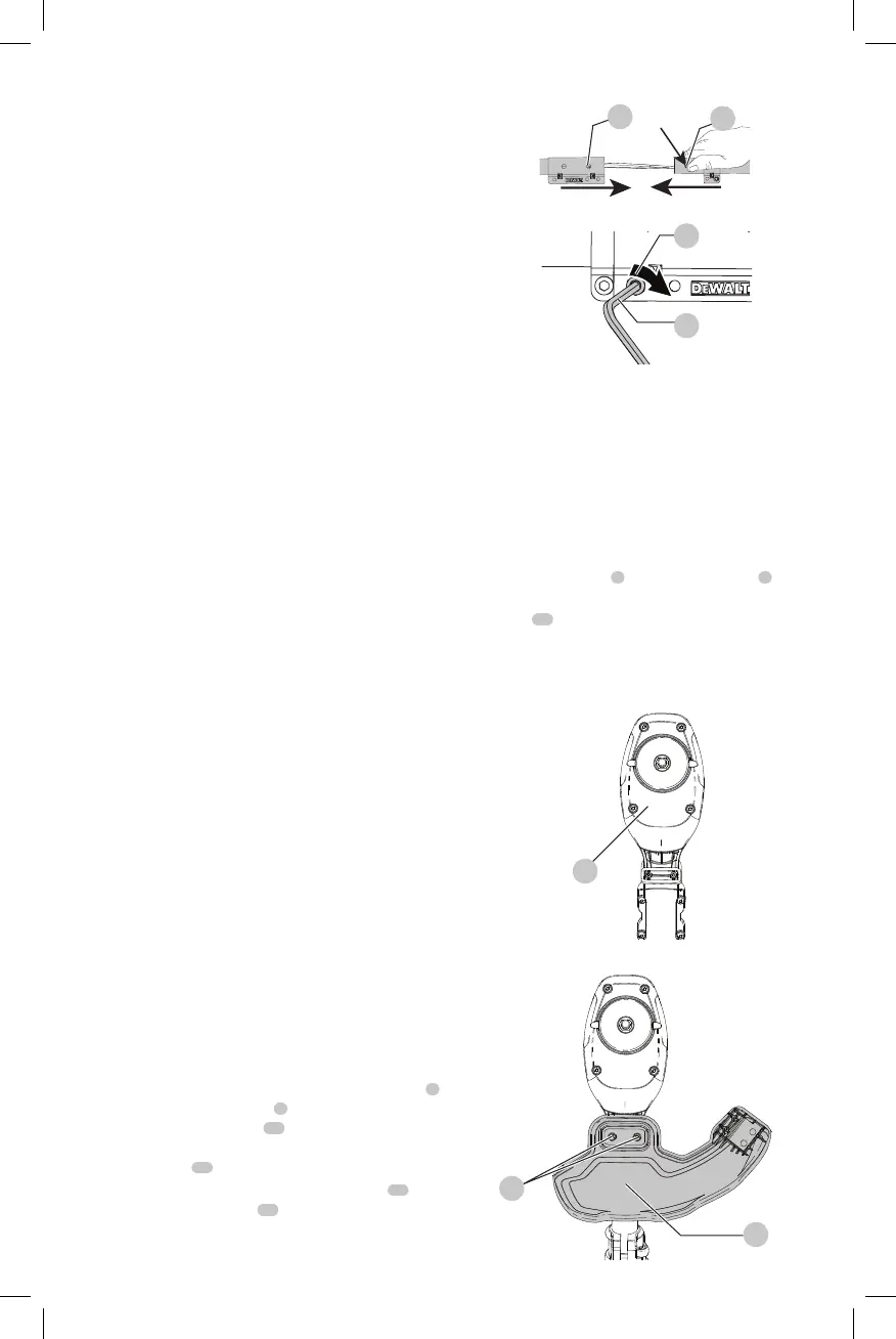
ASSEMBLY FIG. A, D, E
Assembling the Pole
1. To assemble the pole, line up the upper trimmer pole
5
and the lower trimmer pole
6
as shown in Fig. A. Press
down the latching button
15
and slide the upper pole
into the lower pole. Ensure the latching button engages
the latch hole
14
.
2. Secure the poles by tightening the middle bolt
16
with
the supplied hex wrench
17
as shown in Fig.E.
Fig. D
14
15
Fig. E
17
16
Attaching Guard (Fig. F, G)
WARNING: Never remove the guard.
Damage or personal injury couldresult.
WARNING: NEVER OPERATE
APPLIANCE WITHOUT GUARD FIRMLY IN PLACE.
The guard must always be properly attached on the
appliance to protect theuser.
1. Assemble the guard
8
to the motor housing
4
.
2. Using a cross head screwdriver, insert the 2 guard
screws
18
and tightensecurely.
NOTE: An extended coverage guard is available (sold
separately) for extra coverage if desired. Use replacement
guard Part NumberN688823.
Fig.F
4
Fig.G
18
8
 Loading...