15
ENGLISH
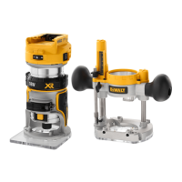
When using the fixed base, one hand should be on top of the
battery and the other hand around the fixed base (Fig.N1).
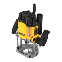
When using the plunge base, grasp the side handles firmly as
shown in Fig.N2.
Starting and Stopping the Motor (Fig.A)
CAUTION: Before starting the tool, clear the work area
of all foreign objects. Also keep firm grip on tool to resist
startingtorque.
CAUTION: To avoid personal injury and/or damage to
finished work, always allow the power unit to come to a
COMPLETE STOP before putting the tooldown.
To turn unit on, depress the side of the dust-protected switch
3
that reads “ON” and corresponds to the symbol “I.” To turn the
unit off, depress the side of the switch that reads “OFF” and
corresponds with the symbol “O.”
Cutting with the Fixed Base (Fig. C)
Set up the router to use the fixed base by following the
instructions in the Assembly and Adjustmentssection.
After the router is set-up, install the battery pack as shown
in Fig.C, then set your router speed (refer to Choosing
RouterSpeed).
NOTE: Always feed the router opposite to the direction in which
the cutter isrotating.
Cutting with the Plunge Base, DCW604 Only
(Fig.A)
NOTE: The depth of cut is locked in the plunge base's default
state. The plunge lock requires user actuation to enable the
"release to lock" plungemechanism.
1. Depress the plunge lock lever
16
and plunge the router
down until the bit reaches the setdepth.
2. Release the plunge lock lever
16
when desired depth
isreached.
NOTE: Releasing the plunge lock lever automatically locks
the motor inplace.
Proper Hand Position (Fig. N1, N2)
WARNING: To reduce the risk of serious personal injury,
ALWAYS use proper hand position asshown.
WARNING: To reduce the risk of serious personal
injury, ALWAYS hold securely in anticipation of a
suddenreaction.
OPERATION
Instructions for Use
WARNING: Always observe the safety instructions and
applicableregulations.
WARNING: To reduce the risk of serious personal
injury, turn tool off and disconnect battery pack
before making any adjustments or removing/
installing attachments or accessories. An accidental
start-up can causeinjury.
CAUTION: Turn the router on before plunging the
cutter head into theworkpiece.
1. Unlock the plunge mechanism by pulling down the plunge
lock lever
16
. Gently push down on the two handes to
plunge the router down as far as it will go, allowing the bit
to just touch theworkpiece.
2. Lock the plunge mechanism by releasing the plunge lock
lever
16
.
3. Loosen the depth adjustment rod
15
by turning the thumb
screw
41
anticlockwise.
4. Slide the depth adjustment rod
15
down so that it meets
the lowest turret stop
14
.
5. Slide the zero adjuster tab
42
on the depth adjustment
rod down so that the top of it meets zero on the depth
adjustment scale
43
.
6. Grasping the top, knurled section of the depth adjustment
rod
15
, slide it up so that the tab
42
aligns with the
desired depth of cut on the depth adjustment scale
43
.
7. Tighten the thumb screw
41
to hold the depth adjustment
rod inplace.
8. Keeping both hands on the handles, unlock the plunge
mechanism by pulling the plunge lock lever
16
down. The
plunge mechanism and the motor will move up. When
the router is plunged, the depth adjustment rod will hit
the turret stop, allowing the router to reach exactly the
desireddepth.
Using the Rotating Turret for Stepped Cuts
(Fig.M)
If the depth of cut required is more than is acceptable in a
single pass, rotate the turret so the depth rod
15
lines up with
taller turret stop initially. After each cut, rotate the turret so the
depth stop lines up with shorter post until the final depth of cut
isreached.
WARNING: Do not change the turret stop while the
router is running. This will place your hands too near the
cutterhead.
Fine Adjustment of Routing Depth (Fig.M)
The knurled knob
44
at the bottom end of the depth
adjustment rod can be used to make minoradjustments.
1. To decrease the cutting depth, rotate the knob clockwise
(looking down from the top of therouter).
2. To increase the cutting depth, rotate the knob anticlockwise
(looking down from the top of therouter).
NOTE: One complete rotation of the knob results in a change of
about 1 mm indepth.
Removing the Motor from the PlungeBase
(Fig.M)
1. Remove the battery pack from the motor. Refer to Inserting
and Removing the BatteryPack from the Tool.
2. Open the locking lever
40
on thebase.
3. Grasp the motor unit with one hand and the base with the
other hand, pull motor from theplungebase.
 Loading...