40
English
NOTICE: Avoid possible damage to the collet. Never tighten the
collet without a bit.
TO REMOVE THE BIT
1. Remove the motor unit from the base unit, see Motor Quick
Release.
2. Depress the spindle lock button (E) to hold the spindle shaft in
place while turning the collet nut (U) counterclockwise with the
wrench provided.
To loosen using the “manual ratchet” method:
a. Without removing the wrench from the collet nut (U), release
pressure on the spindle lock button (E).
b. With the wrench still on the collet nut (U), reverse the loosening
direction to reset the wrench position.
c. Depress the spindle lock button (E) again and turn the wrench
counterclockwise.
d. Repeat the procedure until the collet nut (U) is loose and the bit
can be removed.
Collets
NOTE: Never tighten the collet without first installing a router bit in
it. Tightening an empty collet, even by hand, can damage the collet.
To change collet sizes, unscrew the collet assembly as described
above. Install the desired collet by reversing the procedure. The collet
and the collet nut are connected. Do not attempt to remove the collet
from the collet nut.
Locking Lever Adjustment (Fig. 4)
Excessive force should not be used to clamp the locking lever. Using
excessive force may damage the base.
When the locking lever is clamped the motor should not move in the
base.
Adjustment is needed if the locking lever will not clamp without
excessive force or if the motor moves in the base after clamping.
To adjust the locking lever’s clamping force:
1. Open the locking lever (I).
S
FIG. 4
2. Using a hex wrench turn
locking lever adjustment
screw (S) in small increments.
Turning the screw clockwise
tightens the lever, while turning
the screw counterclockwise
loosens the lever.
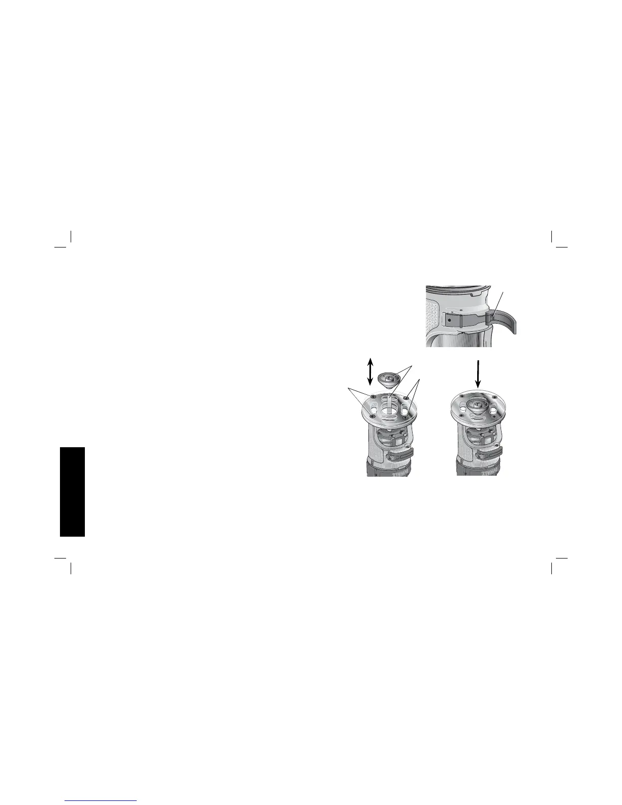
FIG. 5B
FIG. 5A
FF
FF
T
Centering the Subbase (Fig. 5)
If you need to adjust, change, or replace the subbase, a centering tool
is recommended, refer to Accessories. The centering tool consists of
a cone and a pin.
 Loading...