ENGLISH
7
Kerf indicators
16
are also located on the inside of the foot
plate to keep the saw square whencutting.
Cut Length Indicator (Fig. H)
The markings on the side of the foot plate show the length
of the slot being cut into the material at the full depth of the
cut. The markings are in increments of 1/8" (3.2mm).
Fig. H
OPERATION
WARNING: To reduce the risk of injury, turn unit
off and disconnect it from power source before
installing and removing accessories, before
adjusting or when making repairs. An accidental
start-up can causeinjury.
IMPORTANT: Always make sure the depth adjustment
locking lever is in the down position before operatingsaw.
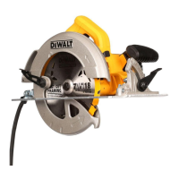
Trigger Switch (Fig. A)
WARNING: To reduce the risk of serious personal
injury, hold saw with both hands when starting
the saw to avoidkickback.
Press the trigger switch
1
to turn the tool on. Release the
trigger switch to turn the tooloff.
NOTE: This tool has no provision to lock the trigger in
the on position and should never be locked on by any
othermeans.
Changing Blades (Fig. A, I–L)
IMPORTANT: Most replacement blades come with a round
arbor center opening which must be knocked out so a
diamond-shaped arbor center is exposed. Only blades with
a diamond-shaped arbor center can be used on thissaw.
NOTICE: Never install a blade without removing the knockout.
Lack of blade engagement will cause the blade to come into
contact with other parts of the saw causing tooldamage.
To Remove Knockout
WARNING: ALWAYS use eye protection. All
users and bystanders must wear eye protection that
conforms to ANSI Z87.1.
WARNING: Make sure that bevel adjusting locking
lever is tight and secure after using it to remove
knockout. If blade adjustment shifts while cutting it
may cause binding andkickback.
Fig. I
17
17
Place the round center hole of the blade into the notch
17
on the top of the bevel adjustment lever
8
. Grasping the
saw and blade firmly, pull until the knockout pops out. The
diamond-shaped arbor center is nowexposed.
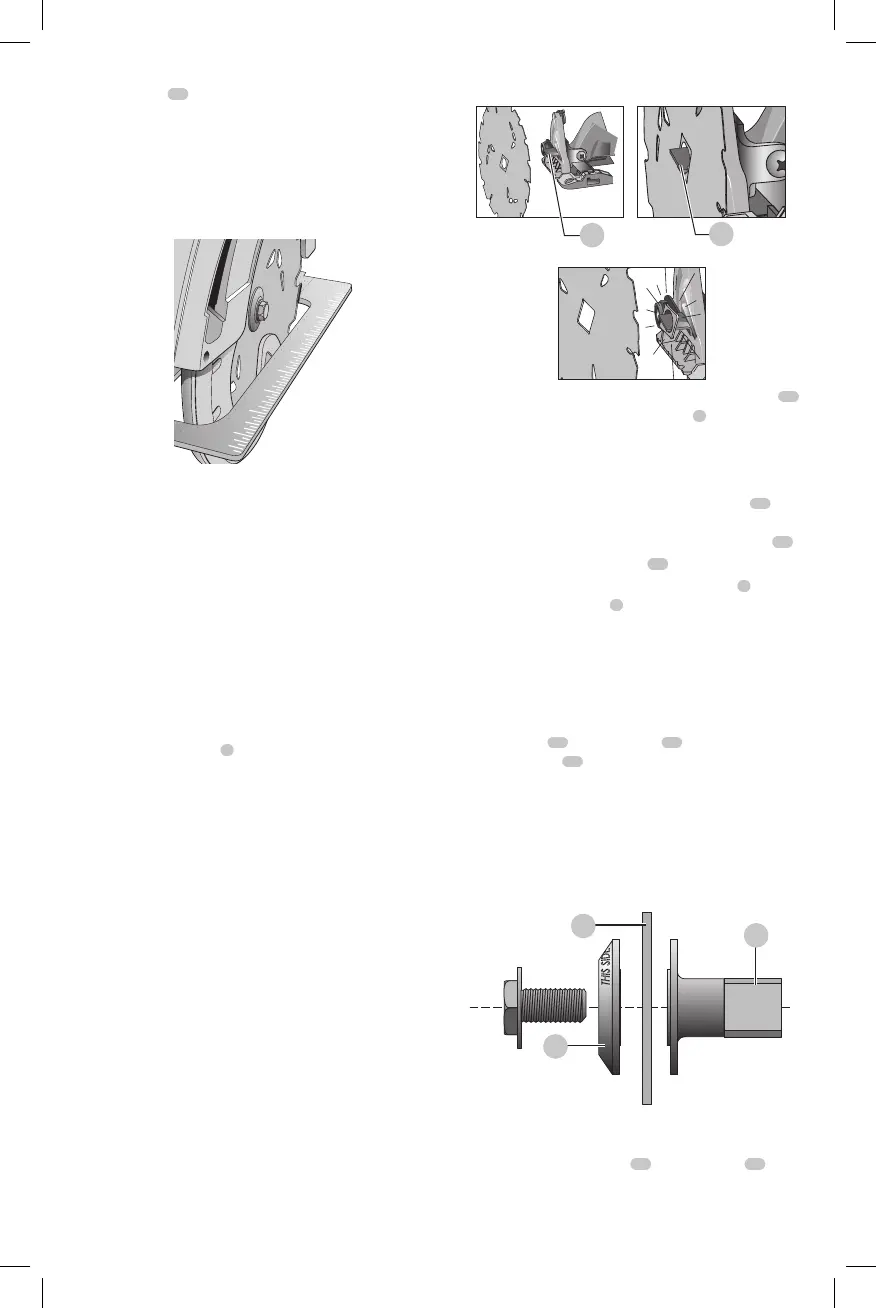
To Install the Blade (Fig. A, J, K)
1. Loosen and remove the blade clamping screw
18
with the wrench provided, by turning it clockwise as
indicated by the arrow on the outer clamp washer
20
.
2. Remove outer clamp washer
20
.
3. Using the lower blade guard retracting lever
3
, retract
the lower blade guard
5
.
IMPORTANT: When retracting the lower blade guard
to install the blade, check the condition and operation
of the lower blade guard to assure that it is working
properly. Make sure it moves freely and does not touch
the blade, foot plate or any other part, in all angles and
depths ofcut.
4. Place blade
21
on saw spindle
22
against the inner
clamp washer
23
, making sure that the blade will
rotate in the proper direction (the direction of the
rotation arrow on the saw blade and the teeth must
point in the same direction as the direction of rotation
arrow on the lower bladeguard).
IMPORTANT: Always ensure the diamond-shaped arbor
center of the blade aligns with the raised diamond-
shaped arbor center on the outer clampwasher.
Fig. K
20
21
22
NOTE: Do not assume that the printing on the saw blade
will always be facing you when properlyinstalled.
5. Place outer clamp washer
20
on saw spindle
22
with
the large flat surface against the blade and the wording
on the outer clamp washer facing you as shown in
FigureK.
 Loading...