13
ENGLISH
When cutting crown molding laying flat, your saw is equipped to accurately
and rapidly set a crown stop, left or right (refer to Instructions for Cutting
Crown Molding Laying Flat and Using the Compound Features)
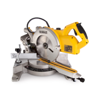
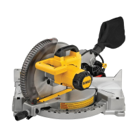
DWS780 (Fig. I)
The crown bevel pawl
52
can be rotated to contact the crown
adjustmentscrew.
To reverse the crown bevel pawl, remove the retaining screw, the 22.5°
bevel pawl
51
and the 30° crown bevel pawl
52
. Flip the crown bevel
pawl
52
so the 33.86° text is facing up. Reattach the screw to secure the
22.5° bevel pawl and the crown bevel pawl. The accuracy setting will not
be affected.
22.5° Bevel Pawls (DWS780, Fig. I)
Your saw is equipped to rapidly and accurately set a 22.5° bevel, left or right.
The 22.5° bevel pawl
51
can be rotated to contact the crown adjustment
screw
49
.
Rail Lock Knob (Fig. A1)
The rail lock knob
7
allows you to lock the saw head firmly to keep it from
sliding on the rails
10
. This is necessary when making certain cuts or when
transporting the saw.
Grooving Stop (Fig. A2)
The grooving stop
28
allows the depth of cut of the blade to be limited.
The stop is useful for applications such as grooving and tall vertical cuts.
Rotate the grooving stop forward and adjust the depth adjustment screw
27
to set the desired depth of cut. To secure the adjustment, tighten the
wing nut
26
. Rotating the grooving stop to the rear of the saw will bypass
the grooving stop feature. If the depth adjustment screw is too tight to
loosen by hand, the provided blade wrench
29
can be used to loosen
thescrew.
Lock Down Pin (Fig. A1)
WARNING: The lock down pin should be used only when carrying
or storing the saw. NEVER use the lock down pin for any cutting
operation.
To lock the saw head in the down position, push the saw head down, push
the lock down pin
12
in and release the saw head. This will hold the saw
head safely down for moving the saw from place to place. To release, press
the saw head down and pull the pin out.
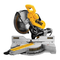
Slide Lock Lever (Fig. K2, U) DWS780 only
The slide lock lever
60
places the saw in a position to maximize cutting of
base moulding when cut vertically as shown in Figure U.
Adjustment
Your mitre saw is fully and accurately adjusted at the factory at the time of
manufacture. If readjustment due to shipping and handling or any other
reason is required, follow the instructions below to adjust your saw. Once
made, these adjustments should remain accurate.
Mitre Scale Adjustment (Fig. H, L)
1. Unlock the mitre lock handle
21
and swing the mitre arm until the
mitre latch button
22
locks it at the 0° mitre position. Do not lock the
mitre lock handle.
2. Place a square against the saw’s fence and blade, as shown. (Do not
touch the tips of the blade teeth with the square. To do so will cause an
inaccurate measure ment.)
3. If the saw blade is not exactly perpendicular to the fence, loosen the
four screws
46
that hold the mitre scale
19
and move the mitre lock
handle and the scale left or right until the blade is perpendicular to the
fence, as measured with the square.
4. Retighten the four screws. Pay no attention to the reading of the mitre
pointer
44
at this time.
Mitre Pointer Adjustment (Fig. H)
1. Unlock the mitre lock handle
21
to move the mitre arm to the
zeroposition.
2. With the mitre lock handle unlocked, allow the mitre latch to snap into
place as you rotate the mitre arm to zero.
3. Observe the mitre pointer
44
and mitre scale
19
shown in figureH.
If the pointer does not indicate exactly zero, loosen the mitre pointer
screw
45
holding the pointer in place, reposition the pointer and
tighten the screw.
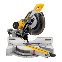
Bevel Square to Table Adjustment
(Fig. A1, A2, I, J, M)
1. To align the blade square to the table, lock the arm in the down
position with the lock down pin
12
.
2. Place a square against the blade, ensuring the square is not on top of a
tooth (Fig. M).
3. Loosen the bevel lock knob
31
and ensure the arm is firmly against the
0° bevel stop.
4. Rotate the 0° bevel adjustment screw (
54
Fig. I, J) with the 13mm
blade wrench
29
as necessary so that the blade is at 0° bevel to the
table.
Bevel Pointer Adjustment (Fig. I, J)
If the bevel pointers
48
do not indicate zero, loosen each screw
47
that
holds each bevel pointer in place and move them as necessary. Ensure the
0° bevel is correct and the bevel pointers are set before adjusting any other
bevel angle screws.
Bevel Stop 45° Right and Left Adjustment
(Fig. A2, I)
To adjust the right 45° bevel stop:
1. Loosen the bevel lock knob
31
and pull the 0° bevel stop
32
to
override the 0° bevel stop.
2. When the saw is fully to the right, if the bevel pointer
48
does not
indicate exactly 45°, turn the left 45° bevel adjustment screw
53
with
the 13 mm blade wrench
29
until the bevel pointer indicates45°.
To adjust the left 45° bevel stop:
3. Loosen the bevel lock knob and tilt the head to the left.
4. If the bevel pointer does not indicate exactly 45°, turn the right 45°
bevel adjustment screw until the bevel pointer reads 45°.
Adjusting the Bevel Stop to 22.5° (or 30°)
(Fig. A2, I)
NOTE: Adjust the bevel angles only after performing the 0° bevel angle and
bevel pointer adjustment.
To set the left 22.5° bevel angle, flip out the left 22.5° bevel pawl
51
.
Loosen the bevel lock knob
31
and tilt the head fully to the left. If the bevel
pointer
48
does not indicate exactly 22.5°, turn the crown adjustment
screw
49
contacting the pawl with a 10 mm wrench until the bevel pointer
reads 22.5°.
To adjust the right 22.5° bevel angle, flip out the right 22.5° bevel pawl.
Loosen the bevel lock knob and pull the 0° bevel stop
32
to override the 0°
bevel stop. When the saw is fully to the right, if the bevel pointer does not
indicate exactly 22.5°, turn the crown adjustment screw
49
contacting the
pawl with a 10 mm wrench until the bevel pointer indicates exactly 22.5°.
Fence Adjustment (Fig. A1)
The upper part of the fence can be adjusted to provide clearance, allowing
the saw to bevel to a full 49° both left and right.
1. To adjust each fence
14
, loosen the fence adjustment knob
13
and
slide the fence outward.
2. Make a dry run with the saw turned off and check for clearance.
3. Adjust the fence to be as close to the blade as practical to provide
maximum workpiece support, without interfering with arm up and
down movement.
4. Tighten the fence adjustment knob securely.
5. When the bevel operations are complete, relocate the fence.
 Loading...