13
ENGLISH
5. Return the guard bracket to its original position and firmly tighten the
guard bracket screw to hold bracket in place.
WARNING:
• The guard bracket must be returned to its original position and the guard
bracket screw tightened before activating the saw. Failure to do so may
allow the guard to contact the spinning saw blade resulting in damage to
the saw and severe personal injury.
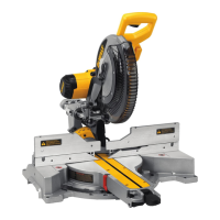
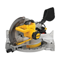
Transporting the Saw (Fig. A1, A2)
WARNING: To reduce the risk of serious personal injury,
ALWAYS lock the rail lock knob, mitre lock handle, bevel lock handle,
lock down pin and fence adjustment knobs before transporting saw.
Never use guards for transporting or liftup.
In order to conveniently carry the mitre saw, a carrying handle
3
has been
included on the top of the sawarm.
• To transport the saw, lower the head and depress the lock down pin
9
.
• Lock the rail lock knob with the saw head in the front position, lock the
mitre arm in the full left mitre angle, slide the fence
11
completely
inward and lock the bevel lock knob
31
with the saw head in the
vertical position to make the tool as compact aspossible.
• Always use the carrying handle
3
or the hand indentations
14
.
Features and Controls
WARNING: To reduce the risk of injury, turn unit off and
disconnect machine from power source before installing and
removing accessories, before adjusting or changing set-ups
or when making repairs. Be sure the trigger switch is in the OFF
position. An accidental start-up can causeinjury.
Mitre Control (Fig.H)
The mitre lock handle
19
and mitre latch button
20
allow you to mitre
your saw to 60° right and 50° left. To mitre the saw, lift the mitre lock
handle, push the mitre latch button and set the mitre angle desired on the
mitre scale
17
. Push down on the mitre lock handle to lock the mitreangle.
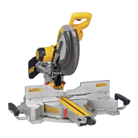
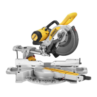
Bevel Lock Knob (Fig. A2)
The bevel lock allows you to bevel the saw 49° left or right. To adjust the
bevel setting, turn the bevel lock knob
31
counterclockwise. The saw head
bevels easily to the left or to the right once the 0° bevel override knob is
pulled. To tighten, turn the bevel lock knobclockwise.
0° Bevel Override (Fig. A2)
The 0° bevel stop override
32
allows you to bevel the saw to the right past
the 0°mark.
When engaged, the saw will automatically stop at 0° when brought up
from the left. To temporarily move past 0° to the right, pull the bevel stop
override
32
. Once it is released, the override will be reengaged. The bevel
stop override can be locked out by twisting the knob 180°.
When at 0°, the override locks in place. To operate the override, bevel the
saw slightly to theleft.
45° Bevel Stop Override (Fig.I)
There are two bevel stop override levers, one on each side of the saw.
To bevel the saw, left or right, past 45°, push the 45° bevel override
lever
50
rearward. When in the rearward position, the saw can bevel past
these stops. When the 45° stops are needed, pull the 45° bevel override
leverforward.
Crown Bevel Pawls (Fig.I)
When cutting crown molding laying flat, your saw is equipped to accurately
and rapidly set a crown stop, left or right (refer to Instructions for Cutting
Crown Molding Laying Flat and Using the Compound Features)
The crown bevel pawl
52
can be rotated to contact the crown
adjustmentscrew.
To reverse the crown bevel pawl, remove the retaining screw, the 22.5°
bevel pawl
51
and the 30° crown bevel pawl
52
. Flip the crown bevel
pawl
52
so the 33.86° text is facing up. Reattach the screw to secure the
22.5° bevel pawl and the crown bevel pawl. The accuracy setting will not
beaffected.
22.5° Bevel Pawls (Fig.I)
Your saw is equipped to rapidly and accurately set a 22.5° bevel, left or right.
The 22.5° bevel pawl
51
can be rotated to contact the crown adjustment
screw
49
.
Rail Lock Knob (Fig. A1)
The rail lock knob
4
allows you to lock the saw head firmly to keep it from
sliding on the rails
7
. This is necessary when making certain cuts or when
transporting thesaw.
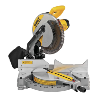
Grooving Stop (Fig. A2)
The grooving stop
28
allows the depth of cut of the blade to be limited.
The stop is useful for applications such as grooving and tall vertical cuts.
Rotate the grooving stop forward and adjust the depth adjustment
screw
27
to set the desired depth of cut. To secure the adjustment, tighten
the wing nut
26
. Rotating the grooving stop to the rear of the saw will
bypass the grooving stop feature. If the depth adjustment screw is too tight
to loosen by hand, the provided blade wrench
29
can be used to loosen
thescrew.
Lock Down Pin (Fig. A1)
WARNING: The lock down pin should be used only when
carrying or storing the saw. NEVER use the lock down pin for any
cuttingoperation.
To lock the saw head in the down position, push the saw head down, push
the lock down pin
9
in and release the saw head. This will hold the saw
head safely down for moving the saw from place to place. To release, press
the saw head down and pull the pinout.
Slide Lock Lever (Fig.J, T)
The slide lock lever
57
places the saw in a position to maximize cutting of
base moulding when cut vertically as shown in FigureT.
Adjustment
Your mitre saw is fully and accurately adjusted at the factory at the time of
manufacture. If readjustment due to shipping and handling or any other
reason is required, follow the instructions below to adjust your saw. Once
made, these adjustments should remainaccurate.
Mitre Scale Adjustment (Fig.H, K)
1. Unlock the mitre lock handle
19
and swing the mitre arm until the
mitre latch button
20
locks it at the 0° mitre position. Do not lock the
mitre lockhandle.
2. Place a square against the saw’s fence and blade, as shown. (Do not
touch the tips of the blade teeth with the square. To do so will cause an
inaccurate measure ment.)
3. If the saw blade is not exactly perpendicular to the fence, loosen the
four screws
46
that hold the mitre scale
17
and move the mitre lock
handle and the scale left or right until the blade is perpendicular to the
fence, as measured with thesquare.
4. Retighten the four screws. Pay no attention to the reading of the mitre
pointer
44
at thistime.
Mitre Pointer Adjustment (Fig.H)
1. Unlock the mitre lock handle
19
to move the mitre arm to the
zeroposition.
2. With the mitre lock handle unlocked, allow the mitre latch to snap into
place as you rotate the mitre arm tozero.
3. Observe the mitre pointer
44
and mitre scale
17
shown in FigureH.
If the pointer does not indicate exactly zero, loosen the mitre pointer
screw
45
holding the pointer in place, reposition the pointer and
tighten thescrew.
 Loading...