About the development board Basic description
Digi Connect ME, Wi-ME, ME 9210, Wi-ME 9210 Hardware Reference Manual
21
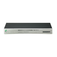
Connectors, Switches and LEDs Board Description Markers 1-5
1 2 3 4 5
Secondary Serial
Port, P2
Primary Port LEDs, CR5
-CR18
GPIO Switch
Bank, SW3
Prototyping
Area, P4
JTAG Header,
P12
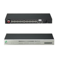
Connectors, Switches and LEDs Board Description (continued) Markers 6-10
6 7 8 9 10
232 Enable Jumper
Block, P5
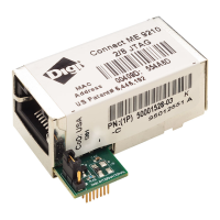
Embedded Module
Connector, P10
JTAG
Connector, P11
Primary Serial
Port, P1
GPIO Port,
P7
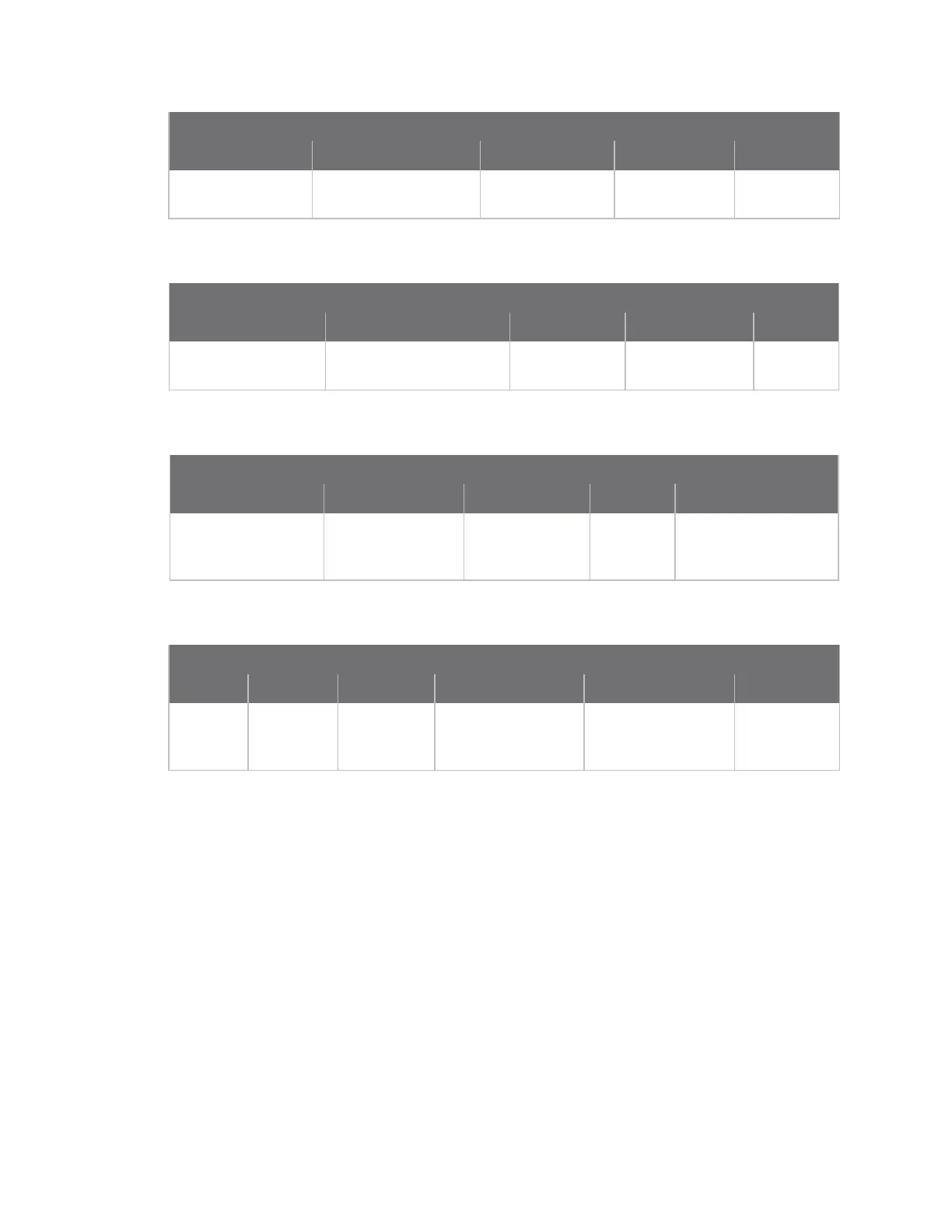
Connectors, Switches and LEDs Board Description (continued) Markers 11-15
11 12 13 14 15
Digital I/O LEDs,
CR19 -CR23
Logic Analyzer
header, P3
POE Source LED,
CR24
Reset
Switch,
SW4
User Pushbuttons,
SW1 & SW2
Connectors, Switches and LEDs Board Description (continued) Markers 16-21
16 17 18 19 20 21
Power
Jack, P15
On/Off
switch,
SW5
Secondary
Port LEDs
CR1-CR4
-48V DC output from
module P13
12V output from PoE
module P14
Current
Measurement
Option P8
n Port descriptions
n Connectors and blocks
n Switches and push buttons
n Development board LEDs
n Power jack P15
See the following figures for placement of either module onto the development board.
 Loading...