Programming considerations LEDs
Digi Connect ME, Wi-ME, ME 9210, Wi-ME 9210 Hardware Reference Manual
37
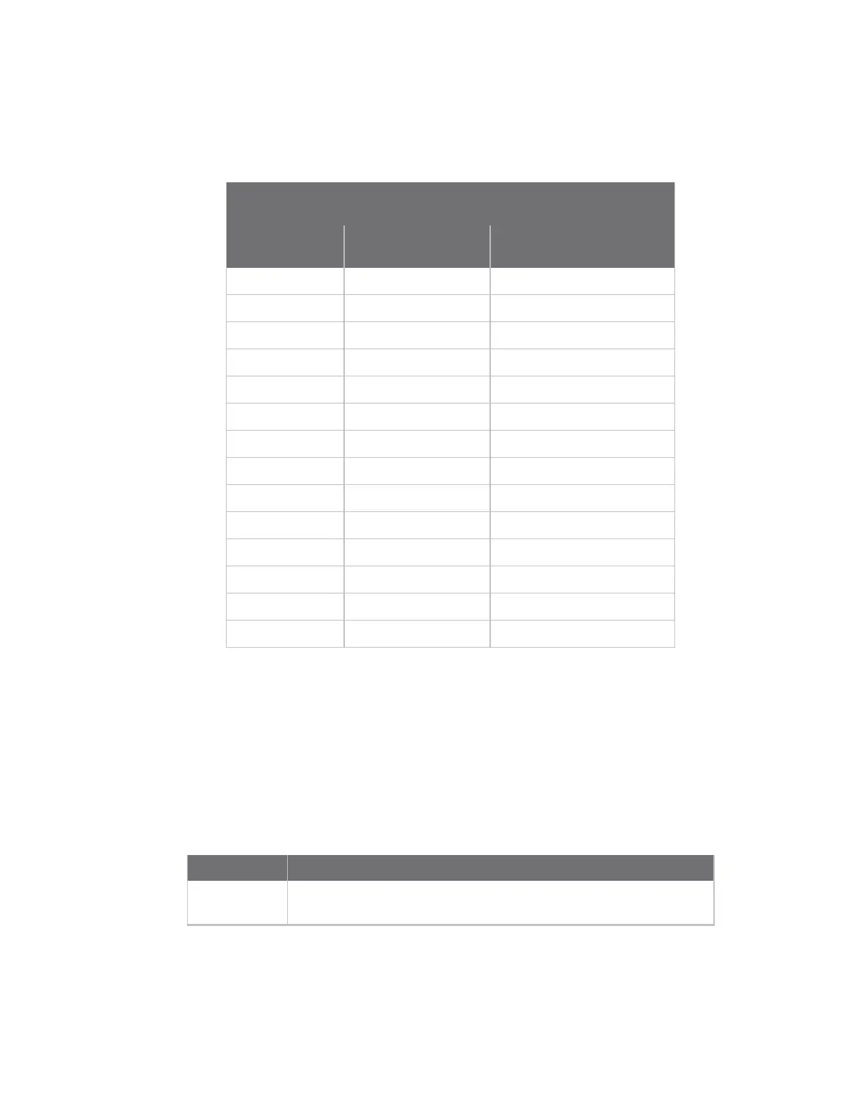
Module JTAG interface pinout
The following table provides signal header pinout information for the Digi Connect ME JTAG pin and
the Development Board JTAG Connector (P11) pin.
Module JTAG Interface Connector
Pin Assignments
JTAG Signal ME JTAG pin #
JTAG Connector (P11) pin
#
+3.3V 1 2
GND 2 1
TRST# 3 4
GND 4 3
TDI 5 6
GND 6 5
TMS 7 8
GND 8 7
TCK 9 10
RXD 10 9
TDO 11 12
SRST 12 11
+3.3V 13 14
TXD 14 13
LEDs
The embedded modules have two types of LEDs:
n An LED connected directly to GPIO pins on the processor and controlled directly in software
n An LED connected to other hardware components (normally the Ethernet hardware) and not
directly programmable by the operating system
The development kit, by default, correctly configures the GPIO connected to the LED as an output and
then uses this LED to represent Ethernet activity.
LED Description
Yellow This is wired directly to Ethernet hardware and provides an indication
of link.
 Loading...