About the development board Connectors and blocks
Digi Connect ME, Wi-ME, ME 9210, Wi-ME 9210 Hardware Reference Manual
25
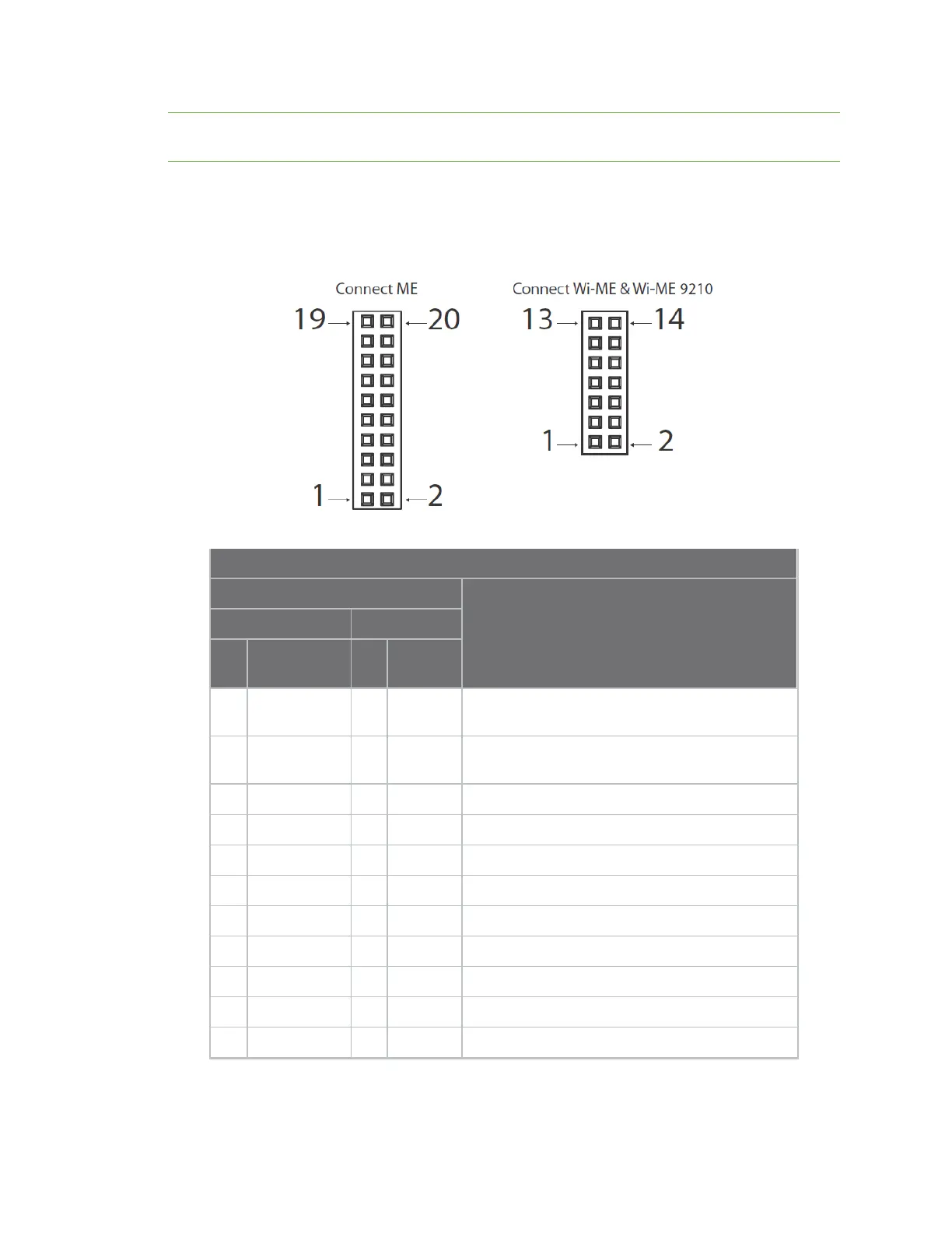
Note The figure shows the connector using the same orientation as shown in the figure titled Board
layout and connector locations.
Embedded module connector pin orientation
Note that the Digi Connect Wi-ME module does not provide pins 1-6. The GPIO pin numbers mentioned
below are used to reference the silkscreen label on the development board, not the actual GPIO
number of the Digi Connect Module. See Module pinout for detailed IO configuration information.
Power and Device Interface Connector Pin Assignments
Signal
Description
ME Wi-ME
Pin
# Function
Pin
# Function
1 ME: Power Pass-Thru+
Wi-ME: Position Removed
2 VETH- ME: Power Pass-Thru-
Wi-ME: Position removed
3-6 Position removed
7 RXD 1 RXD Receive Data (Input)
8 TXD 2 TXD Transmit Data (Output)
9 RTS 3 RTS Request to Send (Output)
10 DTR 4 DTR Data Terminal Ready (Output)
11 CTS 5 CTS Clear to Send (Input)
12 DSR 6 DSR Data Set Ready (Input)
13 DCD 7 DCD Data Carrier Detect (Input)
14 /RESET 8 /RESET Reset
 Loading...