6
DITEC S.P.A - IP1836 - 192C
GB
GENERAL SAFETY PRECAUTIONS
This installation manual is intended for professionally competent personnel only.
Installation, electrical connections and adjustments must be performed in accordance with Good Working Methods and in com-
pliance with applicable regulations.
Before installing the product, carefully read the instructions.
Bad installation could be hazardous. Before installing the product, make sure it is in perfect condition.
For repairs or replacements of products only original spare parts must be used.
1. TECHNICAL DATA
Refer to technical data and CE declaration of conformity contained in the manuals for REX automations.
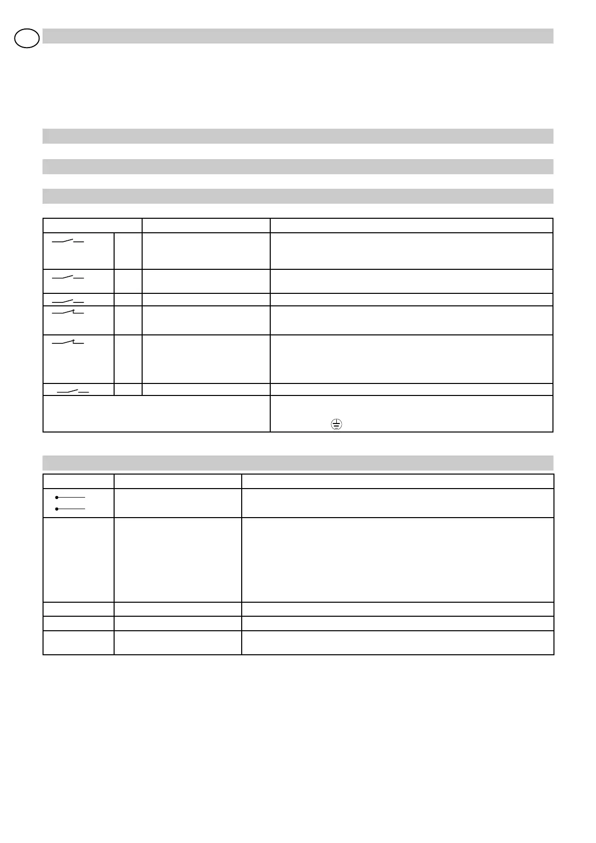
2. ELECTRICAL CONNECTIONS
WARNING: Link up all N.C. contacts (if not used) by means of jumpers. The terminal bearing the same number are equivalent.
2.1 CONTROLS
Control Function Description
1 2 N.O. AUTOMATIC CLOSING A jumper across 1-2 enables the automatic closing.The timer counter
starts at the end of opening manoeuvre. Expired the time, the automatic
closing takes place.
1 2 N.O. CLOSING Closing the contact for less than 3 seconds activates the closing
manoeuvre.
1 3 N.O. OPENING It starts the opening manoeuvre.
1 8 N.C. R E V E R S A L S A F E T Y
CONTACT
Reverses movement (re-opens) during closing.
When door is open, inhibits all operation.
1 9 N.C. STOP It stops any movement. When the contact 1-9 is open, every normal
and emergency function is excluded.
WARNING: When the contact is closed again, the door will resume the
interrupted manoeuvre
27 3 N.O. PARTIAL OPENING It causes a partial opening set via trimmer RP.
CEL A PHOTOCELL Make the connections to the control panel as shown in figure 1.
Attention: In case of installation in particularly noisy environments, ear-
th the terminal
Output/Access. Value Description
1 +
0 -
24 V= / 0,3 A (max)
Accessories power supply. Output for powering of external accessories.
BAT 2x12 V / 2 Ah The battery is charged and kept charged only when the electric panel is
powered from the mains; the battery is used as a buffer or in case of power failure
and is cut out after voltage dropping to below 22V for 30 s. Connect mains
and battery to the electric board at least half an hour before powering the
installation (in order to charge the battery). To power off the electric board, cut
off mains and disconnect the batteries. Attention: Always ensure that the battery
is connected to the electric panel. Periodically, verify the battery efficiency.
BL 24 V= / 1 A Electric lock device. Output for powering of electric lock device.
OPEN Push button to activate the opening maneuver.
RESET Push button to activate the RESET. The first opening and closing to be made at
low speed in order to learn the end-of-travel positions (acquisition phase).
2.2 OUTPUT AND ACCESSORIES
 Loading...