15
EN
Americana and New Generation Refrigerators Wiring Diagrams
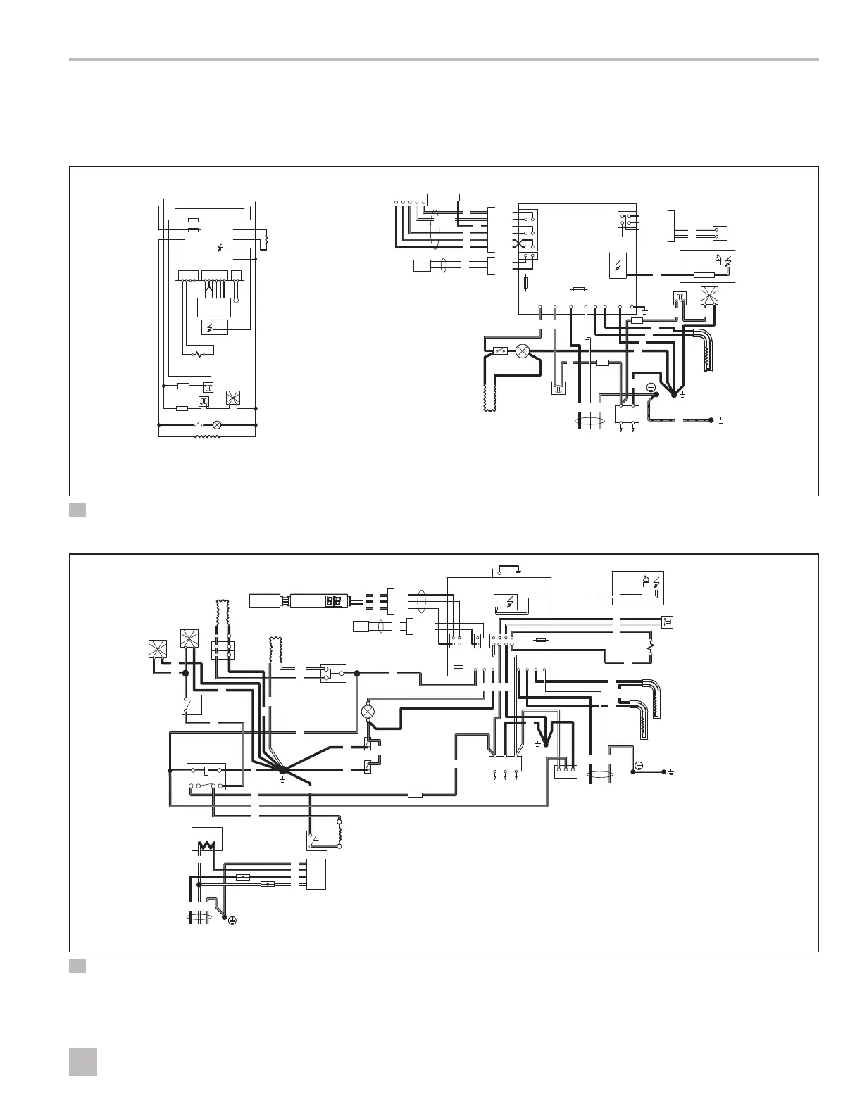
5 Wiring Diagrams
This section provides examples of the wiring for each
refrigerator model.
I
The wiring diagrams shown are best
representations of each refrigerator. Wire colors
may vary.
N
E
T
M
1234 12123456
Display
Board
P3 P1 P2
J4
J6
J5
J7
J2
J8
J10
N
K
3A
5A
+12V
Ground
E
U
V
B
N
T
D
M
S
P
H
F
K
L
L
N
Y
+ –
12VDC
G
O
A
B
J
C
8
4
9
1
1
1
1
1
3
3
9
9
1
2
Orng
3
5
7
3
3 3
1 9 5
6
G
H
F
U
Y
V
3A
J
L
A Circuit Board Power S Chassis Ground
B Fuse 3 A 12VDC
T
Test Port Wire
(internal use only)
C Fuse 5 A 120VAC
D
Upper Eyebrow Circuit
Board
U Ventilator Fan Switch
V Ventilator Fan
E Electrode Y Thermal Fuse
F Thermofuse 1 Black
G Lamp 2 Brown
H Switch Lamp 3 Red
J Heater 120VAC 4 Yellow
K Climate Control Heater 5 Green
L Terminal Block 6 Green/Yellow
M Thermistor 7 Blue
N Solenoid Valve 8 Gray
O Retainer 9 White
P Protective Earth
P1–1
P2–1
P3–4
P3–3
P3–2
P3–1
P2–2
P1–4
P1–2
P1–5
P1–6
P1–3
3 DM2672, DM2682, DM2872, DM2882, DM2652, DM2662,
DM2852, DM2862 (one fan) with and without ice maker
A Control Board M Ventilator Fan Switch Z Protective Earth
B Circuit Board Display N Lamp 1 Black
C Thermistor O Heating Cable 2 Brown
D Climate Control Heater P Switch Lamp 3 Red
E Solenoid Valve R Thermo Fuse 4 Yellow
F Fuse 5A Mini Auto Fuse S Terminal Block 5 Green
G Fuse 5A Glass T Door Ignition Lock 6 Green/Yellow
H Electrode U Heater 120 VAC 7 Blue
J Burner Housing V Retainer 8 Gray
K Heating Cable Girder X Thermostat 9 White
L Door Contact Y Chassis Ground 10 Light Green
A B
12VDC
+ D+
Y
J2
P5 P1P3P4P2P6P7
J3
J1
S
4A
P
O
X
Y
M
N
C
Relay
86 85
87
30
Z
Ice
Maker
L
L
N
N
120VAC
120VAC
C°
C°
Water Valve
L
K
Fan
Fan
D
Z
U
V
–
P1–1
P2–1
Circuit Board Power
P1–2
P2–2
P1–3
3
9
9
9 5
2
F
G
R
9
H
J
E
3
4
7
1
1
3
3
33
3
3
3
3
5
2
1
9
9
3
3
3
3
1
1
1
1
10
10
1
1
1
1
1
1
1
1
1
9 5
7
1
4 RM1350IM (automatic door lock, ice maker & steel doors)
 Loading...