14
v
English
L-2086 Installation
Inspecting the Control/Switch As-
sembly and Electrical Wiring
• Is the thermostat sensor or thermistor properly located and
secured in the return air path and not in direct contact with
any metal objects? (For switch assemblies with two sensing
bulbs, the large one goes in the return air path and the small
one in the discharge air path.)
• Are all wiring harnesses properly secured?
• Are wiring connections made, color to color, correctly at
terminal strips?
• Are plugs properly aligned and securely connected?
• Are all components properly grounded and bonded?
• Are proper sized circuit breakers used?
• Are terminal strips located in a dry, safe place and properly
covered?
Charging the System with Re-
frigerant
Self-contained units are precharged from the factory and do not
need further charging. If you are installing a self-contained system,
skip this section and proceed to “Initial Startup”.
The following instructions should be followed in evacuating and
charging a Cruisair remote condensing unit system with R-22.
Some special ordered units contain refrigerant other than R-22.
Please follow the special charging procedures included with
the unit.
Notice
US federal law prohibits the intentional release of refrig-
erant gases into the environment, including the R -22 re-
frigerant used in most Cruisair air conditioning systems.
Special care must be taken when installing, charging,
and servicing Cruisair equipment to prevent any loss of
equipment. Only EPA certied technicians with the prop-
er equipment should perform service on the refrigerant
circuit of the system.
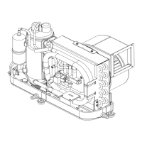
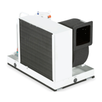
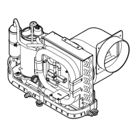
Charging a New System
There are three refrigerant circuit components in a Cruisair re-
mote condensing unit system: the condensing unit, the cooling/
heating unit and the copper r
efrigerant lines. The condensing
unit is shipped from the factory charged with approximately the
right amount of refrigerant needed for the whole system.
The procedure will be to evacuate the nitrogen and air from the
cooling unit and the copper tubing, then release the refrigerant
from the condensing unit into the entire system. To facilitate
this procedure, there is a special evacuation port (red cap)
located on the base valve of the condensing unit .This port has
a schrader valve so you can evacuate and vapor charge the
lines and cooling unit without releasing the refrigerant in the
condensing unit.
You will need the following tools to complete the
charging procedure:
• R-22 container (typically the disposable-type container
color-coded green for R-22)
• four-valve gauge manifold with self-closing ttings on the
charging hoses
• vacuum pump
• base valve wrench and hand tools
• accurate thermometer
Proceed as follows:
1. Make sure all are joints are well made and tight.
2. Do not touch the condensing unit base valve stem covers
or white port caps. Remove the red port cap on the dis
-
charge (right side) base valve (or on a eld-inst
alled in-line
tee tting).
3. Connect the vacuum pump hose to the vacuum pump.
Connect the refrigerant supply line to the refrigerant
container (making sure the refrigerant container valve is
OFF). Connect the low pressure gauge hose, to the red
capped port. At this point, do not connect the high pressure
charging hose to anything.
4. Close all four gauge manifold valves.
5. Energize the vacuum pump and open the manifold valves
for the vacuum pump, the refrigerant container and the red-
capped access port.
6. As the pump operates, you will see the low pressure test
gauge fall to a vacuum. When the vacuum reaches 28
in. Hg close the vacuum pump valve and turn the vacu
-
um pump off. Leave the system for 15 minut
es and then
observe the gauge. If any vacuum has been lost, look
for leaks, especially at are joints. Then return to step #3
above and re-evacuate the system.
7. Open the vacuum pump valve and leave the vacuum pump
operating for at least 6 hours, until a vacuum of at least 29
in. Hg is achieved. Close the vacuum pump valve and turn
the vacuum pump off. Wait one hour. If no vacuum is lost,
proceed with charging. If any leaks are indicated, reinspect
are joints for leakage, and return to step #3 above to
re-evacuate the system.
8. Open the refrigerant container valve slowly and allow gas
to enter the system until the low pressure gauge rises to
zero. You have now vapor charged the evacuated lines and
cooling/heating unit with refrigerant to a gauge pressure of
zero. Close the refrigerant container valve.
9. Remove the low pressure gauge hose from the red capped
port. Replace and tighten the red cap.
 Loading...