8
v
English
L-2086 Installation
Installing The Cooling/Heating
Unit
This section applies only to remote condensing unit systems. If
you are installing a self-contained unit, skip this section and go
to “Installing The Seawater Cooling System”.
Safety Warning
A Cruisair cooling/heating unit should never be placed
such that it can circulate carbon monoxide, fuel vapors
or other noxious fumes into the boat’s living spaces.
Failure to follow this precaution could result in serious
injury or death.
Ignition Protection Warning
Cooling/heating units do not meet federal requirements
for ignition protection. Do not install in spaces containing
gasoline engines, tanks, LPG/CPG cylinders, regulators,
valves or fuel line ttings. Failure to comply may result in
injury or death.
Safety Warning
Do not terminate air handler condensate drain lines with-
in 3 feet (1m) of any outlet of engine exhaust systems,
nor in a compartment housing an engine or generator,
nor in a bilge, unless the drain is properly connected to a
sealed condensate or shower sump pump. Exhaust and/
or bilge fumes can travel up a drain line and mix with the
return air blowing into living areas.
Selecting the Site
Because of the diversity of available cooling/heating units,
there is a great deal of exibility in selecting the location. Typi-
cally the unit is located low in the cabin, with the discharge grill
as high as possib
le for good cooling performance and away
from the return air for proper air circulation.
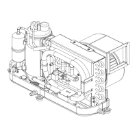
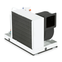
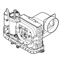
There are basically 2 types of cooling/heating units, draw-
through and blow-through. Figures 5 and 6 show typical cool
-
ing/heating unit installations.
1
. Draw-through units typically have squirrel-cage blowers
that are strong enough to push air through ducting to the
discharge grill.
2. Blow-through units use a fan or blower to blow air across
the evaporator coil for direct discharge through a grill. The
discharge air from these units should not be ducted.
Some cooling/heating units are designed for overhead use,
and may be mounted below a ybridge console or seating. This
setup will draw return air through the overhead, with discharge
air either directly blown back down into the area or ducted to
overhead grills.
It is not necessary for the evaporator coil to be placed directly
in front of the return air grill, but an unobstructed path must be
available for the air to get to the coil. A 2” (50mm) space in front
of the evaporator coil must be maintained.
Site Location Checklist
• Unit is not located in an engine room or near an internal
combustion engine
• There is no obstruction of airow from return air grill to coil
• Accessible for service and maintenance, including the return
air lter
• Adequate space for and condensate drain connections
• Flat, horizontal and sturdy mounting location
• Condensate drain can be run continuously downhill from
unit to overboard tting or sump
• Space is sealed from the bilge or outside air
• Maximum copper tubing run between condensing unit and
cooling unit is 50 ft. (15m)
Mounting the Cooling/Heating Unit
Mount the cooling/heating unit so that the condensate drip pan
is beneath the unit. Some models require a mounting frame or
mounting leg kit, which is supplied separately. Other models
have integral mounting frames or the condensate pan itself
is the mounting base. See individual spec sheets for specic
guidelines.
Route the condensate drain hose steadily downhill so that the
condensate ows freely to an overboard tting or sump. Do not
permit condensate to puddle in the bilge. Some Cruisair cool
-
ing/heating units have two condensate drains, one at each end.
It is recommended that you use both drains for best results. If
you choose to use only one condensate drain, plug the other.
Be careful when bending the extension tubes on the evapora
-
tors. Do not allow the tubing to kink and do not twist or bend
the tubing at the connection point close t
o the coil or the joints
may crack. If bending by hand make large radius bends. Use a
tube bender if a tight bend is required.
Installing the Refrigerant Tubing
Use refrigerant-grade soft copper tubing of the correct sizes to
connect the cooling/heating unit to the condensing unit. Note
that tee-joints will be needed if more than one cooling/heat
-
ing unit is used with a single condensing unit. The tees must
be properly oriented to provide best efficiency. (See Figure 7,
Refrigerant Line Size Chart.)
Only use refrigerant-grade seamless soft copper tubing. Never
use any type of plastic or rubber hose or tubing.
The refrigerant tubes can run uphill, downhill or sloping as re
-
quired and can have as many bends as necessary. Avoid sharp
bends that could result in kinks in the tubing. The cooling/heat-
 Loading...