- 8 -
Hole for drain
water hose
Hose
Boiler
casing
NDR1292
CONNECTIONS
Gas connection
Hook up to the gas supply line is accomplished at the manual
gas valve, which is furnished with a 3/8” SAE (UNF 5/8” -18)
male fl are connection. All completed connections should be
examined for leaks using a solution of liquid detergent and
water.
The gas supply system must incorporate a pressure regulator
to maintain a supply pressure of not more than 11 inches water
column. When testing the gas supply system at test pressures:
> 1/2 psi• - the refrigerator and its individual shutoff valve
must be disconnected from the gas supply piping system.
1/2 psi • - the appliance must be isolated from the gas
supply piping system by closing its individual manual shut-
off valve.
If detailed instructions on the installation and connection to
the gas supply are required, please contact your dealer or
distributor.
Testing LP gas safety shut off
The gas safety shut off must be tested after the refrigerator is
connected to LP gas supply.
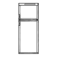
RM2354, RM2454, RM2554, DM2662, DM2663,
DM2862, DM3862, NDM1062 & NDR1292
To test the gas safety shut off, follow these steps:
Start the refrigerator. Switch to GAS mode. 1.
Check that the gas fl ame is lit and the GAS mode 2.
indicator lamp is on.
Close the manual gas shutoff valve at the back of the 3.
refrigerator.
Wait for approx. 6 minutes. The CHECK indicator 4.
lamp should be lit and the GAS mode indicator lamp
should be off.
Remove the protection cover. 5.
Open the manual gas shutoff valve. Do not change 6.
any button positions on the control panel.
Apply a non corrosive commercial bubble solution 7.
to the burner jet orifi ce. No bubbles should appear at
the opening of the burner jet orifi ce. The presence of
bubbles indicates a defective gas safety shutoff, and
service is required.
If no bubbles are present at the burner jet orifi ce, 8.
rinse it with fresh water. Be careful not to damage the
burner jet orifi ce.
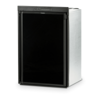
DRAIN WATER HOSE
Drill a hole through fl ooring. To avoid damage to the hose,
the hole must be positioned so that the hose doesn’t touch the
boiler casing. Seal around the hose that goes through the drilled
hole and ensure that it does not kink when run through the
fl oor. Check to make sure that the supplied hose is long enough
in order for the water to drain outside of the vehicle. If not, the
installer will have to supply the extra length of hose.
Drill the hole in the
cut out opening of
the base plate
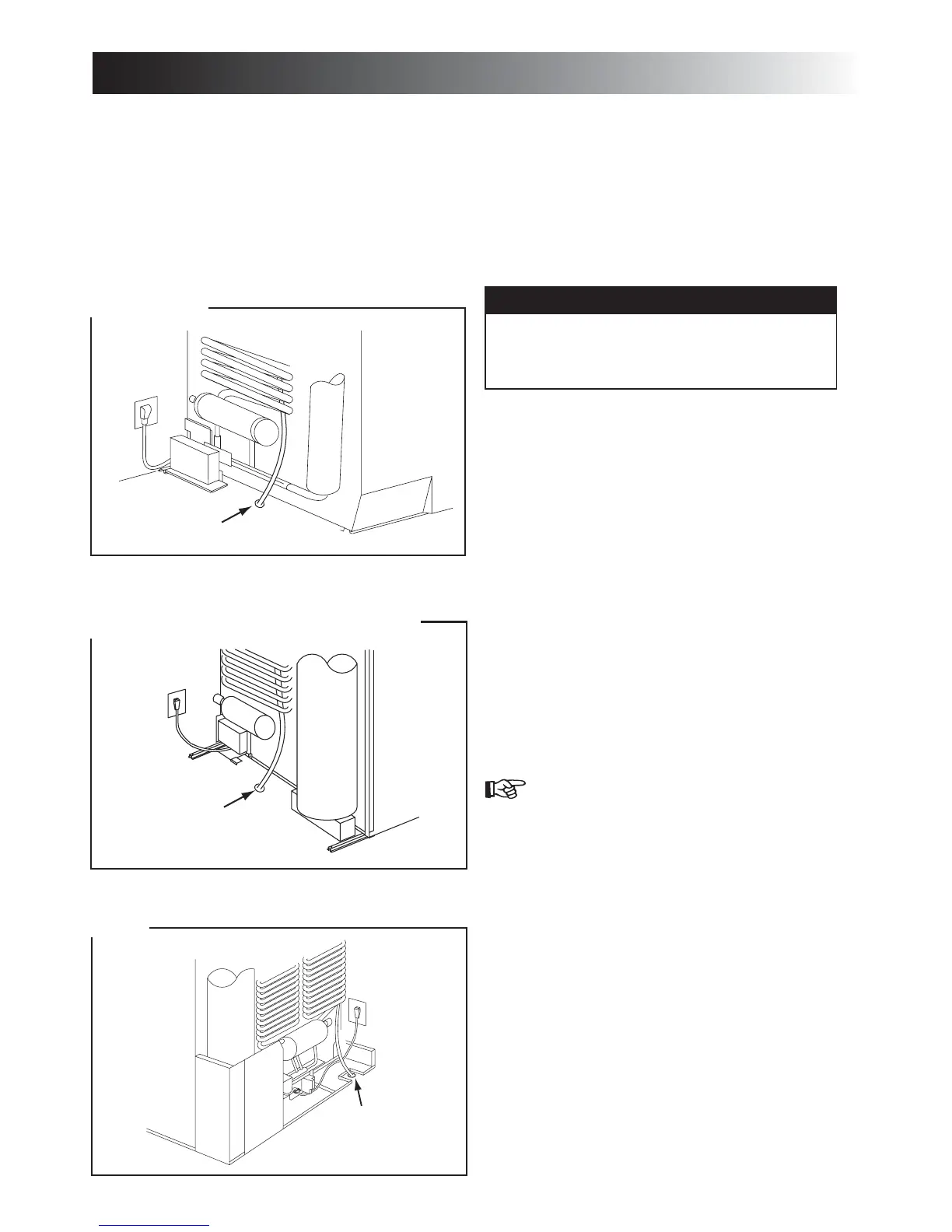
Hole for drain
water hose
Boiler
casing
Hose
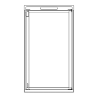
RM2451, RM2454, RM2551, RM2554, DM2652, DM2662,
DM2663, DM2852, DM2862, DM3862 & NDM1062
Hole for drain
water hose
Boiler
casing
Hose
RM2351 & RM2354
INSTALLATION PROCEDURE
WARNING
EXPLOSION HAZARD. Never use an open
fl ame to check for gas leaks. Failure to heed this
warning could cause an explosion resulting in
death or severe personal injury.
6
!
 Loading...