3
DIAGNOSTIC SERVICE MANUALDIAGNOSTIC SERVICE MANUAL
DIAGNOSTIC SERVICE MANUALDIAGNOSTIC SERVICE MANUAL
DIAGNOSTIC SERVICE MANUAL
DometicDometic
DometicDometic
Dometic
® ®
® ®
®
RM3604/3804 AESRM3604/3804 AES
RM3604/3804 AESRM3604/3804 AES
RM3604/3804 AES
®®
®®
®
RefrigeratorsRefrigerators
RefrigeratorsRefrigerators
Refrigerators
SECTION 1SECTION 1
SECTION 1SECTION 1
SECTION 1
AA
AA
A
C C
C C
C
VV
VV
V
OLOL
OLOL
OL
TT
TT
T
AA
AA
A
GE REQGE REQ
GE REQGE REQ
GE REQ
UIREMENTSUIREMENTS
UIREMENTSUIREMENTS
UIREMENTS
The refrigerator is a 120 volt AC, 60 Hz appliance. The
proper operating range is 100 to 132 volts. Check the AC
volts at the receptacle where the refrigerator is attached.
If voltage is outside of the proper operating range, correct
the power source problem.
SECTION 2SECTION 2
SECTION 2SECTION 2
SECTION 2
AA
AA
A
C COMPONENTS —C COMPONENTS —
C COMPONENTS —C COMPONENTS —
C COMPONENTS —
HEAHEA
HEAHEA
HEA
TING ELEMENTTING ELEMENT
TING ELEMENTTING ELEMENT
TING ELEMENT
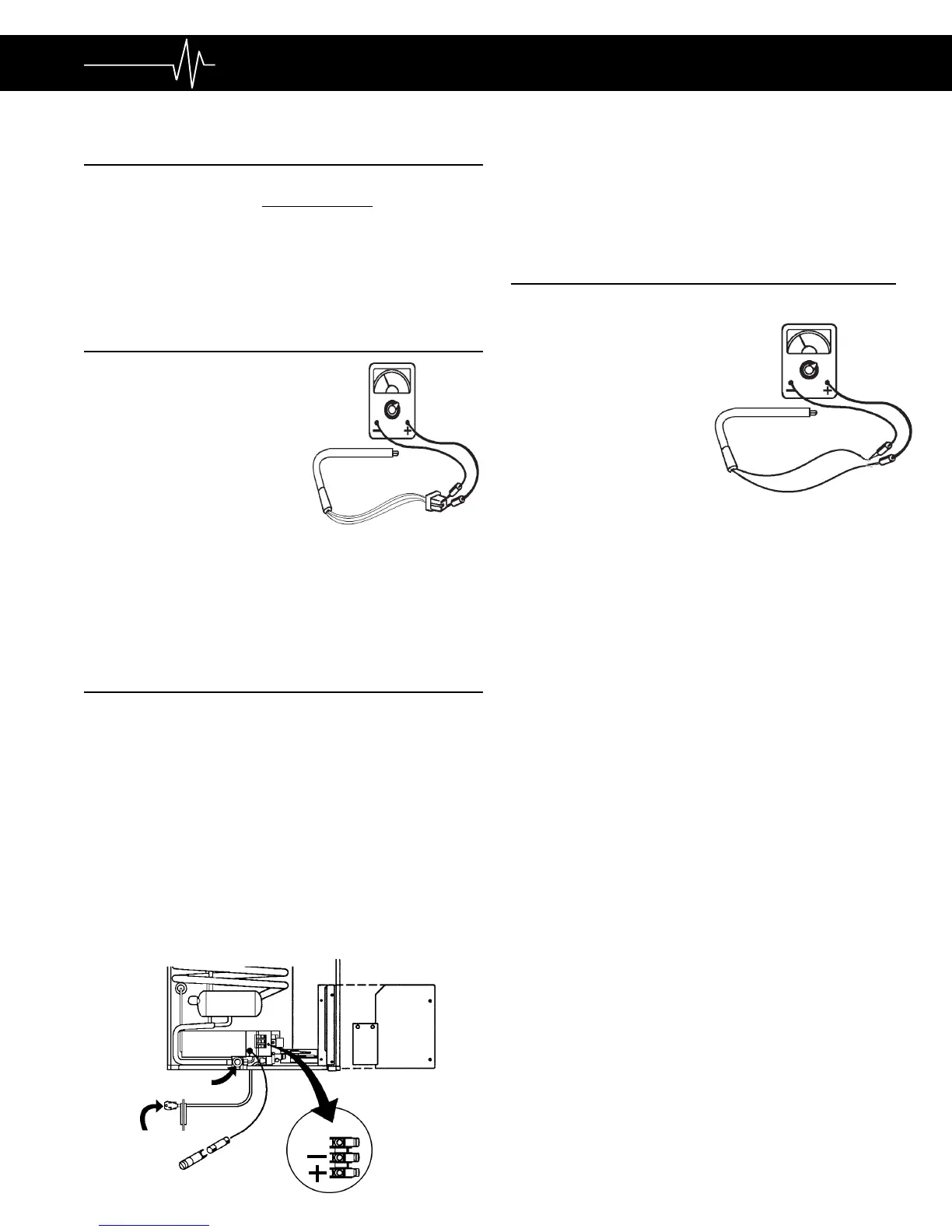
The heating element is designed to
deliver a predetermined amount of
heat to the cooling unit. To check
a heating element, remove the
heater leads from the printed
circuit board and measure for
proper resistance across the
two leads with a properly
calibrated ohm meter. This
check is to be done with the
heating element at room temperature. The proper ohms
for RM3604 is 48 and RM3804 is 44 with a tolerance of
ten percent. If the resistance is outside the tolerance
range, replace the heating element.
SECTION 3SECTION 3
SECTION 3SECTION 3
SECTION 3
DC DC
DC DC
DC
VV
VV
V
OLOL
OLOL
OL
TT
TT
T
AA
AA
A
GE REQGE REQ
GE REQGE REQ
GE REQ
UIREMENTSUIREMENTS
UIREMENTSUIREMENTS
UIREMENTS
For the refrigerator to operate on any mode, DC voltage
must be supplied to the terminals at the rear of the
refrigerator and must be connected directly to the battery
of the RV. The operational range is 10.5 to 15 volts DC.
Connecting the refrigerator to an unregulated converter
can result in improper operation of the refrigerator. Do not
use the body or chassis of the RV as a substitute for
either of the two conductors. Proper polarity is crucial for
operation of the refrigerator. Check for proper voltage at
the positive and negative terminals at the back of the
refrigerator. If power is outside the operational range,
correct the power supply problem. The power supply to
the refrigerator must be fused. Maximum fuse size: 25
amp for RM3604 and RM3804.
3-PRONG PLUG
FOR 120V AC
FUSE LINK
3AMP
MANUAL GAS
SHUTOFF VALVE
IGN.
LOCK
COVER
TERMINAL
BLOCK
With the refrigerator operating on AC or gas mode, if
voltage to the refrigerator slowly drops to or below 9.5
volts DC, the gas flame will come and will not be thermo-
stat controlled. Low DC volts (below 9.5) could cause
over-cooling.
SECTION 4SECTION 4
SECTION 4SECTION 4
SECTION 4
DC COMPONENTSDC COMPONENTS
DC COMPONENTSDC COMPONENTS
DC COMPONENTS
4.14.1
4.14.1
4.1
HEATING ELEMENTHEATING ELEMENT
HEATING ELEMENTHEATING ELEMENT
HEATING ELEMENT
The heating element is
designed to deliver a
predetermined amount of
heat to the cooling unit.
Check the heating
element with ohms
resistance using a prop-
erly calibrated ohm meter.
This check is to be done
with the element at room
temperature. The proper ohms for RM3604 and
RM3804 DC heating element is .67 with a tolerance
range of ten percent. If the heating element is
outside this range, replace it.
NOTENOTE
NOTENOTE
NOTE: It will take a very precise ohm meter to
accurately read this measurement. If a precise ohm
meter is not available, a continuity reading will
indicate an open or complete circuit. If an open
circuit is the test result, replace the element.
4.24.2
4.24.2
4.2
THERMOSTATTHERMOSTAT
THERMOSTATTHERMOSTAT
THERMOSTAT
The thermostat operates on DC volts and regulates the
inside refrigerator temperature on all modes, by
making and breaking the circuit to the printed circuit
board. The internal mechanism breaks contact (conti-
nuity) when adequate cabinet temperature has been
reached. Check the thermostat for continuity. This
check should be made at room temperature with the
thermostat turned all the way to MAX. Another check
would be to use a jumper wire with insulated clips and
bypass the thermostat.
NOTENOTE
NOTENOTE
NOTE: Use care when doing this test. Do not short to
thermostat casing. Also remove jumper after testing is
completed.
If the above test allows the refrigerator to operate and/
or the continuity test proves the thermostat to be
defective, replace the thermostat. A defective thermo-
stat would cause insufficient cooling, no cooling and
freezing on all modes.
4.34.3
4.34.3
4.3
SOLENOID VALVESOLENOID VALVE
SOLENOID VALVESOLENOID VALVE
SOLENOID VALVE
The solenoid valve assembly is a
safety valvesafety valve
safety valvesafety valve
safety valve as well as
a
gas flow valvegas flow valve
gas flow valvegas flow valve
gas flow valve. When the AES selects LP gas opera-
tion, DC volts are sent to the solenoid coil which opens
the internal valve.
 Loading...