5
DIAGNOSTIC SERVICE MANUALDIAGNOSTIC SERVICE MANUAL
DIAGNOSTIC SERVICE MANUALDIAGNOSTIC SERVICE MANUAL
DIAGNOSTIC SERVICE MANUAL
DometicDometic
DometicDometic
Dometic
® ®
® ®
®
RM3604/3804 AESRM3604/3804 AES
RM3604/3804 AESRM3604/3804 AES
RM3604/3804 AES
®®
®®
®
RefrigeratorsRefrigerators
RefrigeratorsRefrigerators
Refrigerators
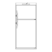
Voltage should
NOTNOT
NOTNOT
NOT
be present between
terminals 85 and 87.
If voltage is present,
the relay is defec-
tive and needs to be
replaced.
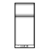
With vehicle ignitionWith vehicle ignition
With vehicle ignitionWith vehicle ignition
With vehicle ignition
switch on and voltageswitch on and voltage
switch on and voltageswitch on and voltage
switch on and voltage
to IGN lock terminal:to IGN lock terminal:
to IGN lock terminal:to IGN lock terminal:
to IGN lock terminal:
Check: Voltage should
be present between
terminals 85 and 86.
If no voltage is
present, check wiring
connections (see
Sec. 7.2), upper
circuit board (see Sec.
4.9), thermostat (see
Sec. 4.2) and circuit board (see
Sec. 4.10).
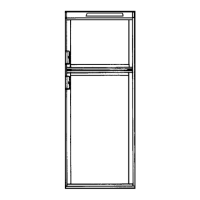
If voltage is present between 85 and 86, voltage should
be present between terminals 85 and 87. If no voltage is
present, the relay is defective.
4.84.8
4.84.8
4.8
DOOR SWITCHDOOR SWITCH
DOOR SWITCHDOOR SWITCH
DOOR SWITCH
The door switch is an open switch when the switch arm
is depressed (interior light should be off). When the
refrigerator door is open the switch is closed (interior
light should be on). Check that the switch assembly is
properly aligned and that it is not broken. Check the
switch assembly for continuity.
NOTENOTE
NOTENOTE
NOTE: To do a continuity check, first be sure all power
to the refrigerator is disconnected or off. Second,
remove all wires from the switch assembly, then check
the switch. After the check, be sure the switch assembly
is wired properly per the wiring diagram.
When the switch arm is depressed, there should NOT
be continuity. When the switch arm is not depressed,
there SHOULD BE continuity. If any of these checks are
incorrect, replace the switch.
4.94.9
4.94.9
4.9
UPPER CIRCUIT BOARD (SWITCH CARD)UPPER CIRCUIT BOARD (SWITCH CARD)
UPPER CIRCUIT BOARD (SWITCH CARD)UPPER CIRCUIT BOARD (SWITCH CARD)
UPPER CIRCUIT BOARD (SWITCH CARD)
1.
ON–OFF SWITCHON–OFF SWITCH
ON–OFF SWITCHON–OFF SWITCH
ON–OFF SWITCH
NOTE: The following checks should be made on the
upper circuit board and harness assembly BEFORE
replacing the upper circuit board or wiring harness.
The checks are to be done with the wiring harness
REMOVED from the lower circuit board.
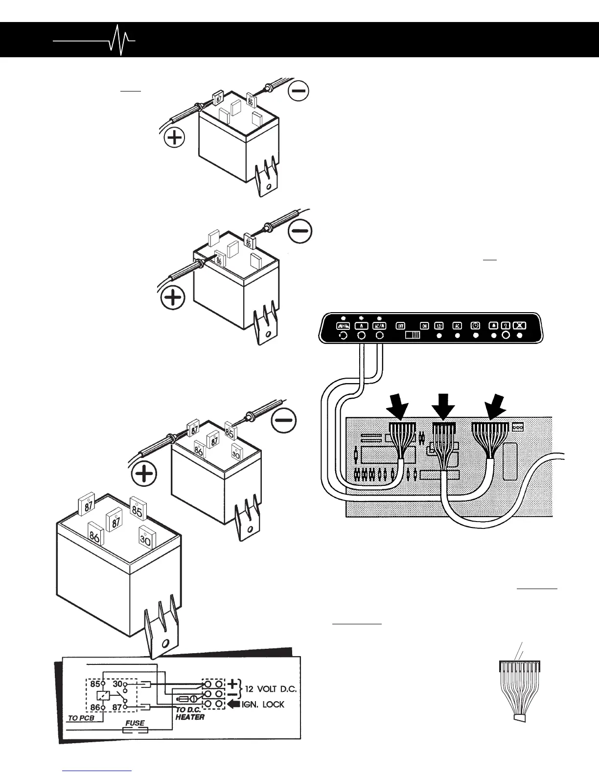
With the switch in the "ON"With the switch in the "ON"
With the switch in the "ON"With the switch in the "ON"
With the switch in the "ON"
positionposition
positionposition
position:
CONTINUITY should be indi-
cated between the orange
terminal to the yellow terminal on
the 10 pin connector.
7-PIN
CONNECTOR
6-PIN
CONNECTOR
10-PIN
CONNECTOR
 Loading...