5
3. Connecting the Toilet Water Supply Lines
The water supply inlet must connect to an adapter which
will adapt to the 1/2-inch MPT connection on the toilet
water valve. (This adapter can be found through a local
supplier or through Dometic.) The water supply must
provide a minimum ow of two (2) gallons per minute
(7.6 liters per minute).
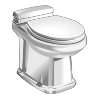
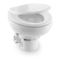
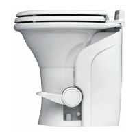
1. Installing the Toilet
For VacuFlush and EcoVac toilet mounting, follow the
instructions in the VacuFlush Installation Guide.
2. Routing and Installing Hose
Before attaching the vacuum hose to a tting, place
two hose clamps over hose end. (All connections must
be double clamped.) Apply liquid dishwashing soap to
outside of hose connector and inside hose. Twist hose
clockwise as it is pushed onto adapter (see Figure 2).
Hose end should be ush against the tting shoulder
when properly installed (see Figure 3). Twist the hose
counter-clockwise before placing it onto the tting. This
will ease installation. All joints should be double clamped
with high quality stainless steel clamps. Make sure
clamp mechanisms are 180° from each other when tight
(see Figure 3). Failure to follow these procedures will
result in vacuum leaks.
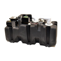
4. Mounting the Vacuum Holding Tank
The Vacuum Holding Tank (VHT) can be located in any
accessible space as long as the 1-1/2 inch hose is not
longer than 20 feet (6.1 m) and its inlet is not higher than
3 feet (.9 m) from the toilet outlet. The VHT must be
mounted horizontally.
Mounting spindles are provided for securing the VHT in
areas that prevent access to the rear mounting feet on
the VHT.
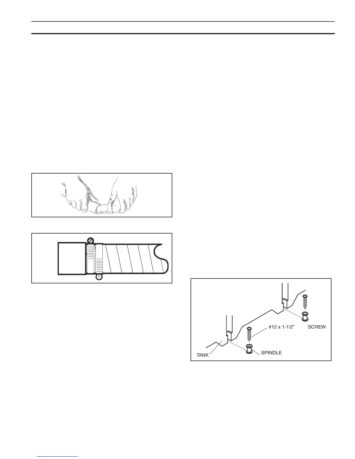
Position the VHT in the space intended. If using mount-
ing spindles, mark holes at rear of tank. After holes
are marked, remove VHT and secure (3) of the spindles
provided to the mounting surface using (3) #12 x 1-1/2
inch long pan head wood screws. Slide the VHT back
so mounting spindles t into slots on tank (see Figure
4). Secure the tank by using the (3) remaining spindles
and (3) #12 x 1-1/2 inch long pan head wood screws on
remaining tank mounts.
If not using the mounting spindles, secure the VHT with
(8) #12 x 1-1/2 inch long pan head wood screws and (8)
at washers on all (8) tank mounts. NOTE: The VHT must
be secured by at least (6) of the (8) mounting feet.
Once the VHT is in place, connect hose from toilet.
(NOTE: Hose insert elbow ttings can be removed from
VHT.)
5. Making Electrical Connections
See the “Wiring Diagram” section of this manual.
6. Completing the Installation
Complete installation of discharge hose from outlet of
VHT to a discharge deck tting or overboard discharge
pump.
Figure 3
Figure 2
INSTALLATION OF COMPONENTS
Figure 4
 Loading...