5
Operation
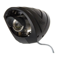
Figure 3: Wiring operation as 3-wire device with 4-20mA output
37
29
2815
141
+24 VDC
0 VDC
+4-20mA
8
10 12 13
11
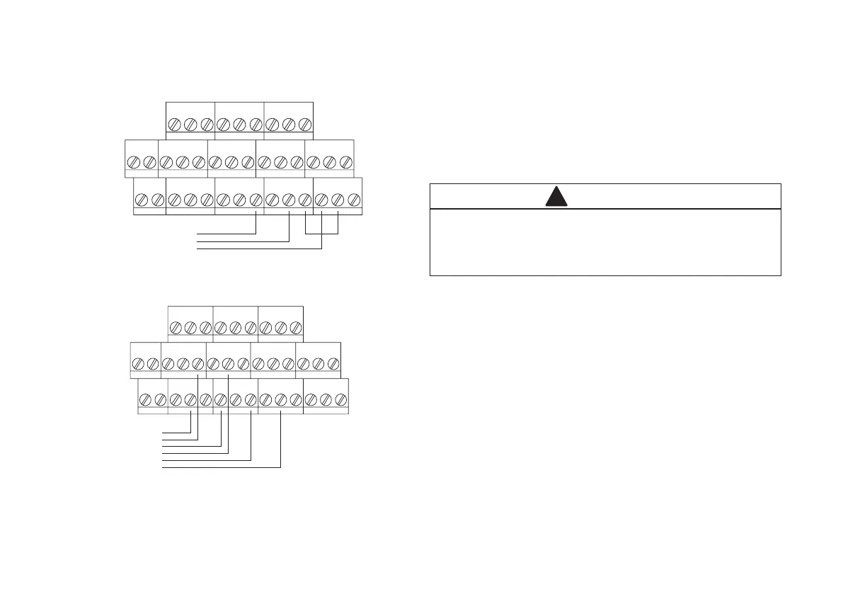
Figure 4: Wiring with relay output
37*
29
2815
141
Fault NC
Fault COM
Alarm NO
8
10
21
19
4
6
0 VDC
+24 VDC
Alarm COM
35*
*Please refer to ‘Note’ on page 3.
Note:
When this equipment is installed within either:
NEC 500 Class 1 Div 1
NEC 505 Class 1 Zone 1
Certifi ed areas then it must be installed using type MC-HL cable (Metal Clad for
Hazardous Locations)
Mechanical Installation
CAUTION
Before replacing the terminal compartment cover ensure the threads
are lightly lubricated using suitable non-setting silicone grease.
Hand-tighten the terminal cover then tighten the locking screw with a
2mm hexagon key (see Technical Specification’ section).
!
Finally the protective cover is fi tted over the housing, to do this:
Briefl y remove the detector from its mounting bracket by slackening the two •
M8 fi xing screws.
Fit the two sides of the cover around the detector itself before aligning •
together and tightening with the 4 securing screws.
Return the detector to its mounting bracket and secure into position by •
tightening the two M8 screws to the specifi ed torque (see section Technical
Data). ENSURE THAT THE DEVICE IS COVERING THE CORRECT
AREA
Unused cable entries must be fi tted with appropriate certifi ed stopping plugs
before commissioning the detector.
The detector is now ready for power on and set-up.

 Loading...