6
Operation
Operation
When the power is initially turned on there is a delay of approximately thirty seconds
where the system performs an internal test and system initialisation.
An optical and hardware check is performed within the testing. If the device has
correct functionality and displays a green LED, it is now ready for fi re detection.
However, if there is a hardware or optical failure within the device the yellow LED
will illuminate to indicate a problem. This will stay illuminated until the problem has
been addressed and remedied by the operator.
The fl ame detector generates a 0-20mA signal to indicate its status (see Maintenance
section); this should be checked during the installation of the detector.
Alternatively the status and operation of the device can be monitored by the colour
of the LED illuminated.
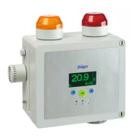
System Status LED Status Visual Indicator
Power On / Running
Green LED indicates successfully
running
System Fault / Failed Optical
Check
Yellow LED indicates a system hardware
fault or optical failure
Fire Detected
Red LED indicates a hazard has been
detected
Maintenance
Observe respective national regulations. (e.g. in Europe 60079-17 applies.)
The Draeger Flame Detector FD10 Range performs an automatic optics test every
30 minutes; this normally takes approximately 10 seconds.
WARNING
The Draeger Flame Detector FD 10 Range contains no user
serviceable parts. In the event of suspected failure, the suspect
unit should be returned to Draeger Safety UK Ltd
NO ATTEMPT SHOULD BE MADE TO DIS-ASSEMBLE THE UNITS
IN HAZARDOUS AREAS!
!
When replacing the detector front cover assembly it is essential for the
function of the detector that the calibration bar in front of the lens is horizontal
when the cover is in place. To do this hand-tighten the front cover and then
back it off a maximum of half a turn until the two locking screws align with the
detector housing. Tighten both locking screws to the specifi c torque (see
Technical Data) using a 2mm hexagon key.
The only servicing requirement to ensure that the detector is fully functional is
to measure the output between 0-20mA as per the table ‘Detector Outputs’
and collaborate these readings to the expected LED colour to be illuminated. In
addition, ensure that the lenses are clean.
 Loading...