PIR sensitivity adjustment
POTENTIOMETER “SENS”– adjustment according to protected area range.
Use the potentiometer to adjust the detection range between 68% and 100%
(factory set to 84%). Rotate the potentiometer clockwise to increase range,
counter-clockwise to decrease range.
Wire size requirements
Use #22 AWG (0.5 mm) or wires with a larger diameter. Use the following
table to determine required wire gauge (diameter) and length of wire between
the detector and the control panel.
Wire Length m 200 300 400 800
Wire Diameter mm .5 .75 1.0 1.5
Wire Length ft. 800 1200 2000 3400
Wire Gauge AWG 22 20 18 16
TESTING
Test procedures
Wait one minute - warm up time after applying 12 Vdc power.
Conduct testing with the protected area cleared of all people.
Walk test
1. Remove front cover. The pulse jumper must be in position 1. The LED must be enabled. 2. Replace the front cover.
3. Start walking slowly across the detection zone. 4. Observe that the detector’s LED lights whenever motion is detected.
5. Allow 5 sec. between each test for the detector to stabilize. 6. After the walk test is completed, the LED may be disabled.
Note: Walk tests should be conducted, at least once a year, to confirm proper operation and coverage of the detector.
TECHNICAL SPECIFICATION
Model LC-100PI
Detection Method Quad (Four element) PIR
Power Input 8.2 to 16 VDC
Current Draw Standby: 8mA (± 5%)Active: 10mA (± 5%)
Temp.
Compensation YES
Alarm Period 2 sec (± 0.5sec)
Alarm Output N.C 28VDC 0.1 A with 27Ohm series
protection resistor
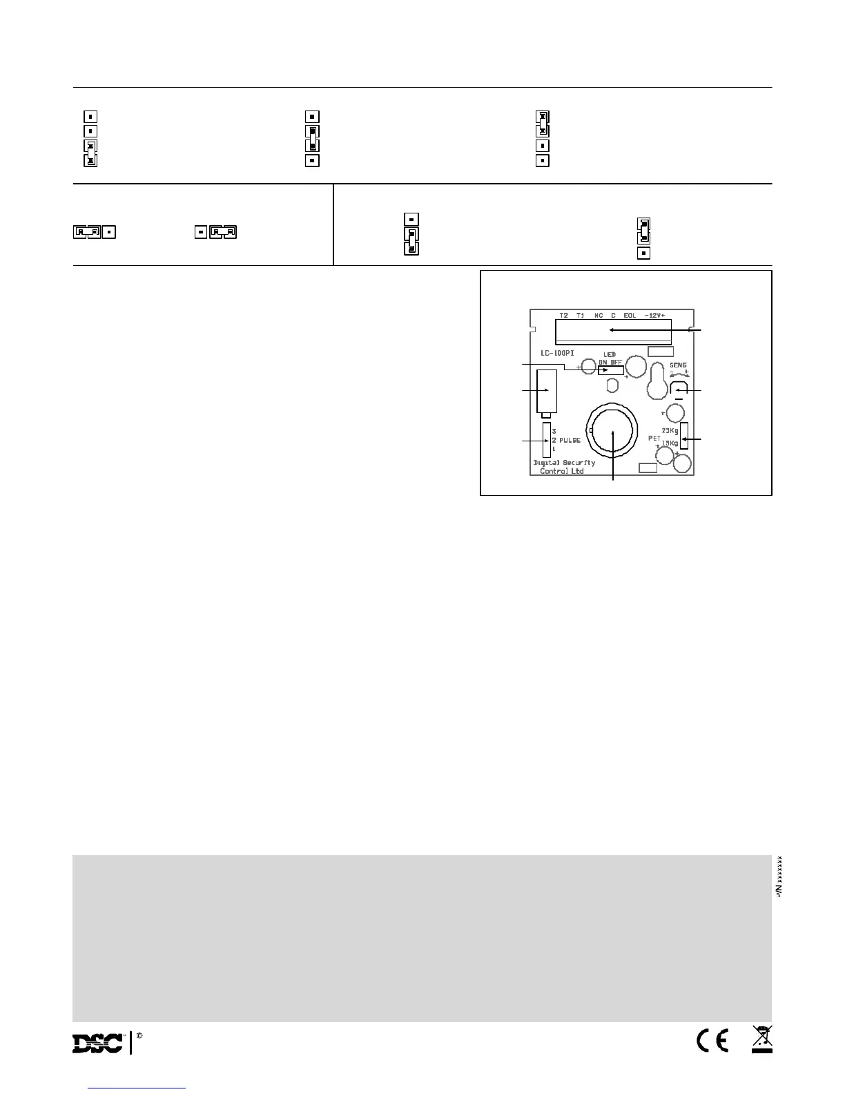
PULSE
3
2
1
PULSE
3
2
1
PULSE
3
2
1
PULSE WIDTH JUMPER SETTING
PET
25Kg
15Kg
PET
25Kg
15Kg
Very stable environment
Position 1
Without PET
Moderate nuisance situation
Position 2
PET up to 15Kg (33.1 Ib)
Relatively high change of false alarms
Position 3
PET up to 25Kg (55 Ib)
LED ENABLE JUMPER SETTING
LED ON LED OFF
PET IMMUNITY JUMPER SETTING
Immunity to an animal
up to 25Kg (55 Ib)
Immunity to an animal
up to 15Kg (33.1 Ib)
LED
JAMPER
TAMPER
PULSE
WIDTH
TAMPER
PET
IMMUNITY
ADJUSTMENT
SENSITIVITY
ADJUSTMENT
BLOCK
CONNECTOR
PYROSENSOR
PCB LAYOUT
Tamper Switch N.C 28VDC 0.1A with 10 Ohm series protection
resistor - open when cover is removed
Warm Up Period 60sec (± 5sec)
LED Indicator LED is ON during alarm
RFI Protection 30V/m 10 - 1000MHz
EMI Protection 50,000V of electrical interference from lightning
or power through
Dimensions 92mm x 62.5mm x 40mm(3.62’’ x 2.46’’ x 1.57’’)
Weight 40gr (1.4oz)
SETTING - UP THE DETECTOR
LIMITED WARRANTY: Digital Security Controls Ltd, warrants that for a period of 12 months from the date of purchase, the product shall be free of defects in materials and workmanship under normal use and that in
fulfillment of any breach of such warranty. Digital Security Controls Ltd shall, at its option, repair or replace the defective equipment upon returns of the equipment to its repair depot. This warranty applies only to defects
in parts and workmanship and not to damage incurred in shipping or handling, or damage due to causes beyond the control of Digital Security Controls Ltd, such as lightning, excessive voltage mechanical shock, water
damage, or damage arising out of abuse, alteration or improper application of the equipment.
The foregoing warranty shall apply only to the original buyer, and is and shall be in lieu of any and all other warranties, whether expressed or implied and of all other obligations or liabilities on the part of Digital Security
Controls Ltd. Digital Security Controls Ltd neither assumes responsibility for, nor authorizes any other person purporting to act on its behalf to modify or to change this warranty, nor to assume for it any other warranty or
liability concerning this product.
In no event shall Digital Security Controls Ltd be liable for any direct, indirect or consequential damages, loss of anticipated profits, loss of time or any other losses incurred by the buyer in connection with the purchase,
installation or operation or failure of this product.
Motion detectors can only detect motion within the designated areas as Shown in their respective installation instructions. They cannot discriminate between intruders and intended occupants. Motion detectors do not
provide volumetric area protection. They have multiple beams of detection and motion can only be detected in unobstructed areas covered by these beams. They cannot detect motion which occurs behind walls, ceilings,
floor, closed doors, glass partitions, glass doors or windows. Any
type of tampering whether intentional or unintentional such as masking , painting, or spraying of any material on the lenses, mirrors, windows or any other part of the detection system will impair its proper operation.
Passive infrared motion detectors operate by sensing changes in temperature. However their effectiveness can be reduced when the ambient temperature rises near or above body temperature or if there are intentional
or unintentional sources of heat in or near the detection area. Some of these heat sources could be heaters, radiators, stoves, barbeques, fireplaces, sunlight, steam vents, lighting and so on.
WARNING: Digital Security Controls Ltd, recommends that the entire system be completely tested on a regular basis. However, despite frequent testing, and due to, but not limited to, criminal tampering
or electrical disruption, it is possible for this product to fail to perform as expected.
Important information: Changes or modifications not expressly approved by Digital Security Controls Ltd could void the user's authority to operate this equipment.
2005 Digital Security Controls Ltd
Toronto, Canada
www.dsc.com