©2014 Tyco Security Products, Toronto, Canada www.dsc.com Tech. Support: 1-800-387-3630
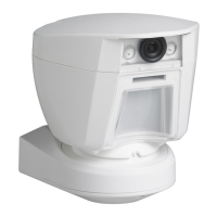
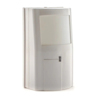
PG9944/8944/4944 Installation
Instructions
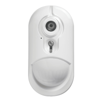
W ireless Ou tdoo r PIR Detecto r wit h C amera
Overview
The PGx944 uses e ight PIR sensors, each ac ting a s a
Qua d detector to accurately and reliably determine
whe ther a n alarm is justified. Features & benefits
include:
l Optimum performance even in poor weather con-
ditions such as snow, rain, dust, wind and direct
sunlight.
l Tamper protection prevents opening and removal
from wall.
l Built-in link quality indicators reduce installation
time by eliminating the need for the installer to
physically approach the control panel.
l Microprocessor-controlled compensation.
l Immunity to pets weighing up to 18 Kg (40lb).
NOTE: Pet immunity fea ture has not been evaluated
to UL 639 or ULC-S306- 03 due to the feature not
being a ddressed in either standa rd.
CAMERA FEATURES
l Color or black & white images
l Auto-setup for brightness and contrast via the con-
trol panel
l Day and night CMOS camera, with IR illumination.
This allows taking pictures in full darkness
l Camera range of 12m (40ft); with IR illumination
10m (33ft)
l Camera operation modes:
l Post alarm – pictures are taken after detec-
tion by detector.
l Visual Verification
Device Setup
WARNING! To c omply with FCC and IC RF exposure
compliance requirements, the PIR detector should be
located at a distance of at least 20 cm from all persons
during normal operation. The antenna s used for this
productmust not be co-located or ope rated in con-
junction with any other antenna or transmitter.
NOTE: The PG Series wire less PIR Motion de tectors
shall be installed and used within an environment that
provides the pollution degree max 2 and overvoltages
category II in NON HAZARDOUS LOCATIONS.
The equipment is designed to be installed only by qual-
ified service pe rsons.
NOTE: To ensure the continued operation of all wire-
less devices after performing a system default, a
global uploa d of all wire less programming via DLS is
re commended before defaulting the system. After
completing the system default, download the wireless
programming.
NOTE: Back tamper switch is required for UL com-
merc ial burglary installations.
BATTERY INSTALLATION
Initial battery installation should be done on a flat sur-
fa ce. After inserting the batteries, the LED flashe s for
60 seconds and the detector enters a 15 minute loc al
diagnostic mode.
NOTE: W hen manually progra mming wireless
devices, if a device has been powered up for more
than 48 hours it cannot be enrolled into the system
until the device has be en tampered and restored.
When progra mming the panel using Quick Enroll, fol-
low the steps detailed in "Enrollment."
NOTE: After restoring a low ba ttery trouble the sys-
tem may take up to 5 minutes to c lear the trouble.
ENROLLMENT
To quick enroll:
1. On a keypad press [*] [8] [Installer Code] [804]
[000].
2. Press and hold the device enroll button until the
LED lights steady and then release the enroll but-
ton while the LED is still lit. A confirmation mes-
sage then appears on the keypad.
3. Press [*] key to confirm ID.
4. Enter [3 digit zone #].
5. Enter [3 digit zone type].
6. Enter [1 digit partition #] for all desired partitions
and press [#]. If using an LCD keypad you can
scroll to the desired partitions and press [*] to
toggle the partition.
7. On an LCD keypad enter the label by using word
library.
To pre -enroll:
1. Remotely configure the unique ID number into the
system. For more information see the HSM2HOST
manual.
2. When on-site, press the device enroll button.
NOTE: If the wireless device has been powered for
more than 48 hours without being enrolled, tamper
and restore the de vice to e nroll it.
PLACEMENT AND WALK TESTING
Before permanently mounting any wireless device,
temporarily mount the device a nd pe rform a Plac e-
ment test. Perform a walk test of the covera ge area at
lea st once a year to ensure that the detector is work-
ing correctly.
1. Tamper the device by removing the cover.
2. Restore the tamper. The device
now enters Placement test
mode for 15 minutes.
3. Trip the device and the red
LED blinks once to identify
that a signal is being sent to the
receiver and then blinks three
times to identify the signal
strength. To perform a walk
test, walk across the far end of
coverage pattern in both dir-
ections. The following table indicates received sig-
nal strength indication.
LED Response Signal Strength
Green LED blinks STRONG
Orange LED blinks GOOD
Red LED blinks POOR
No blinks No communication
IMPORTANT! Only GOOD or STRONG signal
strengths a re acceptable. If you receive a POOR sig-
nal from the device, re -locate it and re- test until a
GOOD or STRONG signal is receive d.
NOTE: For UL/ULC installations, only STRONG sig-
nal levels are ac ceptable. After installation verify the
productfunctionality in conjunction with the c om-
patible re ceivers HSM2HOST9, HS2LCDRF(P)9,
HS2ICNRF(P) 9 and PG9920.
NOTE: For detailed Plac ement instructions refe r to
the control panel Reference Manual.
MOUNTING THE DEVICE
Installation Notes: The top cove r should only be
accessed by authorized service personnel or man-
ufacturer. Do not obscure the de tector field of view
with large objects. Install in position suc h that expec-
ted intruder motion is perpendicular to the zone s of
detection.
Alarms triggered by conditions such as weather, blow-
ing leaves a nd brush, or related environmental con-
ditions, etc., need to be c onsidered when assessing the
installation and a pplication. If nuisance trips are not
tolera ble it is recommende d that the wireless outdoor
intrusion de tection unit is e nrolled in the system to a
zone that is defined as a trouble alarm circuit.
1. Fix the bracket firmly on a stable wall or pillar.
The orientation of the fixed bracket must be as par-
allel as possible to the surveyed ground surface.
2. Mark drilling point
3. Drill
4. Fasten with three long screws
5. Fasten the detector to the bracket with two short
screws.
Adjust the detector's horizontal and
vertical angles according to the
surveyed ground surface. The ver-
tical angle indicator position for
various installation height and cov-
erage distance combinations is
detailed in the following table (the
information refers to a relatively
flat surveyed area. Verify the ver-
tical adjustment by walk-test).
Mounting Height
Coverage Distance
2m
6.7 ft
4m
13 ft
6m
20 ft
8m
26 ft
10m
33 ft
12m
39 ft
3.0m/ 10 ft - 1 2 2 3 3
2.5m/ 8 ft 1 1 2 3 4 4
2.0m/ 7 ft 1 2 3 4 5 5
1.5m/ 5 ft 2 3 4 5 - -
LED Operation
LED Indications Event
Red LED blinks Stabilization (warm-up 60 sec.)
Red LED on 0.2
sec.
Tamper open/close
Red LED 2 blinks
One quad PIR detection in dia-
gnostic mode
Red LED on 2 sec. Intruder alarm
Configuration
To enter the wireless configura tion section e nter
[804][Zone Number].
DEVICE TOGGLE
[001][01] Alarm LED - Default [Y]
Enables the devices LED to
activate when an alarm event
occurs.
[001][04] Supervision - Default [Y]
Enables supervision of the
device.
[001][09] More Options
[03] 24Hr/Night - Default [Y]
Define if motion alarms are
always enabled or only
enabled at night. For UL/ULC
installations night mode is to
used to supplement the pro-
tection covering the detec-
tion area.
DEVICE OPTIONS
[003] Hightraffic Shutdown - Default [01]
Activating this feature helps conserve battery
power when the system is disarmed by con-
figuring a reporting timer. When motion is
detected, the device transmits an alarm to the
receiver and will not report any further events
until the timer expires. Any motion detected
during the configured period will be reported
once the timer expires. No Delay causes the
device to report an alarm each time the
detector is tripped.
[01] Detector
Disabled
(while dis-
armed)
[02] No Delay
[03] 5 second
delay
[04] 15
second delay
[05] 30
second delay
[06] 1m delay
[07] 5m delay
[08] 10m
delay
[09] 20m delay
[10] 60m
delay
[004] Image Brightness - Default [04]
Lightens and darkens the image
[01] Image
Bright
-3
[02] Image
Bright
-2
[03] Image
Bright
-1
[04] Image
Bright
0
[05] Image
Bright
+1
[06] Image
Bright
+2
[07] Image
Bright
+3
[005] Image Contrast - Default [04]
Lightens and darkens the contrast.
[01] Image
Contrast
-3
[02] Image
Contrast
-2
[03] Image
Contrast
-1
[04] Image
Contrast
0
[05] Image
Contrast
+1
[06] Image
Contrast
+2
[07] Image
Contrast
+3
[007] Detection Sensitivity - Default [02]
Selects the sensitivity range of PIR devices.
[01] Low Sens-
itivity
[02] Mid Sens-
itivity
[03] High
Sensitivity
[04] UL Stand-
ard
[011] Camera Toggles
[01] Color -
Default [Y]
[02] High Res.
- Default [Y]
[03] Normal
Res. - Default
[N]
[09] More
Options
[09][01] AC
Power -
Default [N]
SPECIFICATIONS
Caution! Risk of explosion if battery is replaced by
an incorrec t type. Dispose of used batteries according
to the manufacturer's instructions and according to
local rules and regulations. Batteries a re to be
re placed by service persons only.
OPTICAL
Black Mirror Max. Coverage : At least 12 m (40 ft) /
90°
Detec tor Te chnology: 8 independent qua d PIR de tect-
ors operating in true Quad configuration
Pet Immunity: Up to 18 Kg (40 lb)
ELECTRICAL
Input Powe r: Two 3V CR17450 Lithium batteries
Note: For UL installations use Eve Energy Co. CR17450 only.
Battery Life (for typical use ): minimum one year, typ-
ica l 3 years (not ve rified by UL/ULC)
Low Battery Threshold: 4.0 V
Functional
Picture Resolution: 320x240 pixels QVGA
Frame Rate: up to 2 fps (for user)
Alarm pe riod: 2 sec onds
WIRELESS
Frequency Band (MHz): CE Listed PG4944:
433MHz; CE/EN listed PG8944: 868MHz;
FCC/IC/UL/ULC listed PG9944: 912- 919MHz
MOUNTING
Mounting type: W all mounting
Mounting He ight: 1.5 – 3.0 m (5 – 10 ft). Must be 8
fe et for UL/ULC listed installations.
Horizontal Adjustment: -45° to +45°, in 5° steps
Vertical Adjustment: 0° to -10°, in 2.5° steps
ENVIRONMENTAL
Temperature range: - 40ºC to +70ºC (UL/ULC only
verified the range - 35ºC to +66ºC)
Relative Humidity: up to max. 93%RH, non- con-
densing
White Light Immunity: Above 25000 lux
PHYSICAL
Size (H x L x W): 157 x 147 x 124 mm (6- 3/16 x 5-
13/16 x 4- 7/8”)
Weight (with battery): 600 g (21 oz)
COMPATIBLE RECEIVERS
433MHz Band: HSM2HOST4; HS2LCDRF(P)
4;HS2ICNRF(P)4; PG4920
868MHz Band: HSM2HOST8; HS2LCDRF(P)8;
HS2ICNRF(P) 8;PG8920
912-919MHz Band: HSM2HOST9; HS2LCDRF(P)9;
HS2ICNRF(P) 9; PG9920
NOTE: Only device s opera ting in band 912- 919MHz
are UL/ULC listed.
Notice
The PGx944 detector wa s designed to a dhere to
applicable privacy regulations and only processes
data neede d for the primary functionality of the
device. Before using the detector you will be asked to
provide consent with processing of the personal data
that the detec tor may capture. Note that the detector
re cords vide o to secure the best functionality of the
device. The recordings are proc essed secure ly and
automatically erase d on a periodic basis. Based on the
location of the module you may ha ve the obligation to
issue a notice about using it.
The data rec orded through the PGx944 detector are
processed a nd maintained primarily by the data con-
troller. Data c ontroller is the entity that provides mon-
itoring service s to you. You ha ve the right to e nquire
about your data with them. For more information
about the ir privacy practices please c ontact the da ta
controller.
For more information about Tyco privacy practices
please visit our website http://www.tyco.com/privacy.
UL/U LC N ot es
Only model PG9944 operating in the frequency band 912-919MHz is
UL/ULC li sted. The PG9944 has been listed by UL for commercial and
residential burglary appl ications and by ULC for residential burg-