MC • Edition 2023.04 • No. 298 073 Re. -0
8 … 16
9 … 16
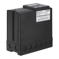
Installation of MPA 4112 and MPA 4114
Installation on DIN rail or
Installation with 2x screw M4, length min. 20 mm
Drill mounting holes with 4.5 mm drill
Place a sealing washer or O-ring underneath to obtain the protection class IP 54.
10. Special functions
Unlock function
Pressing the unlock button allows the MPA to be unlocked when in a locked state.
Actuation time > 0.5 s < 5 s. The device can be unlocked a maximum of ve times in 15 minutes.
Further unlocking is possible only after a waiting period of three minutes.
Enhanced unlock (only using the unlock button in the device)
Resetting the unlock block:
Hold the unlock button > 5 s < 10 s until the display starts ashing, then release the unlock key and press
again.
The “Enhanced unlock” function is active in all operating states of the MPA.
Pressing it during operation results in a safety shutdown and subsequent restart.
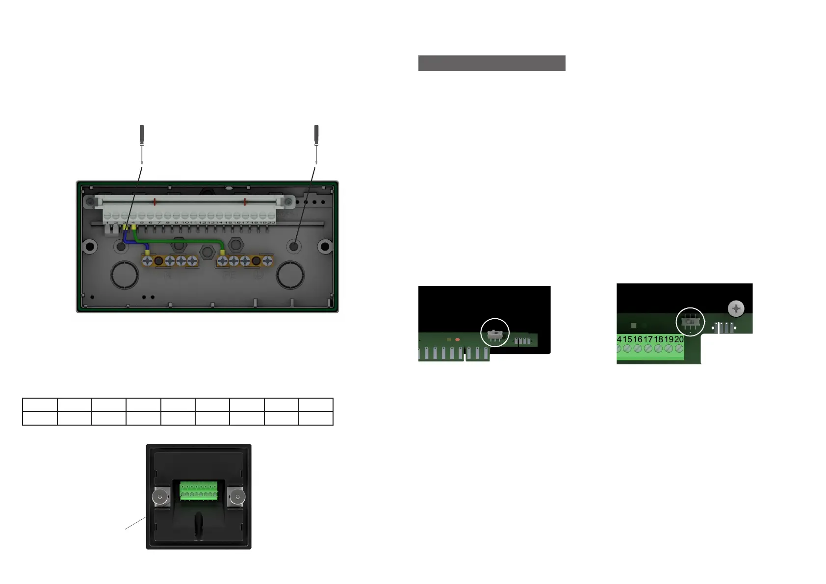
Parameterisation switch
Attention: For a factory-set MPA, the switch must be set to the “Auto” position.
For additional information, refer to the product manual
MPA 4112 and MPA 4114
MPA 4122
Installation of display AM 41
For installation, create a 68 x 68 mm cut-out at the installation location.
The maximum permissible material thickness of the installation surface is 5 mm.
Use connection line AM 41 # 298790, (max. 10 m) to connect the display.
PIN 1 2 3 4 5 6 7 8
Colour White Brown Green Yellow Grey Pink Blue Red
AM 41 plug assignment
Pin 1
 Loading...