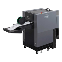
2. INSTALLING PROCEDURE
Turn on the power supply of the DBM-120, and set to the A3 size.
Refer to “6-1. Basic Operation” in the instruction manual of the DBM-120 for details on
setting the paper size.
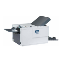
6
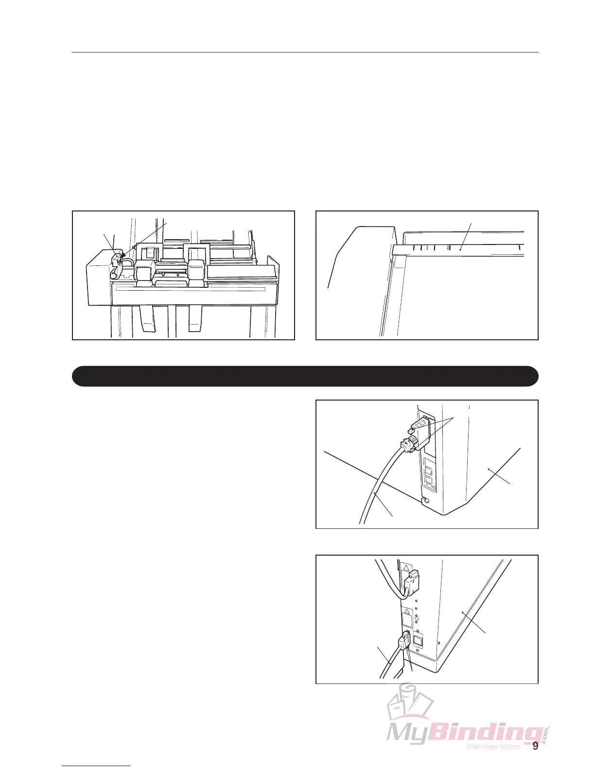
Adjust the A3 mark on the
indication label to this face
LU-HM exit
jam sensor
Indication label of DBM-120
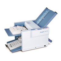
2-7. Connecting the Communication Cable
Connect the communication cable
provided to the connector of the DBM-120.
After connecting, be sure to tighten the
screws.
<< Parts to be used >>
Communication cable q .................................... 1
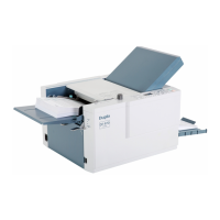
1
Connect the other connector of the
communication cable to the connector (at
the bottom) for connecting the peripheral
devices of the suction collator.
After connecting, be sure to tighten the
screws.
2
Communication cable
Suction collator
Screws
DBM-120
Communication cable
Screws
Adjust at the long holes of the connecting plate so that the A3 mark on the indication label of
the DBM-120 faces the LU-HM exit jam sensor side facing up, and tighten the screws
temporarily secured in step 2 to secure the connecting plate and LU-HM.
7
 Loading...