38
. Self-diagnose for Malfunction
The system provides a unique feature to help service people pin point the sensor malfunction, detail
procedure as below:
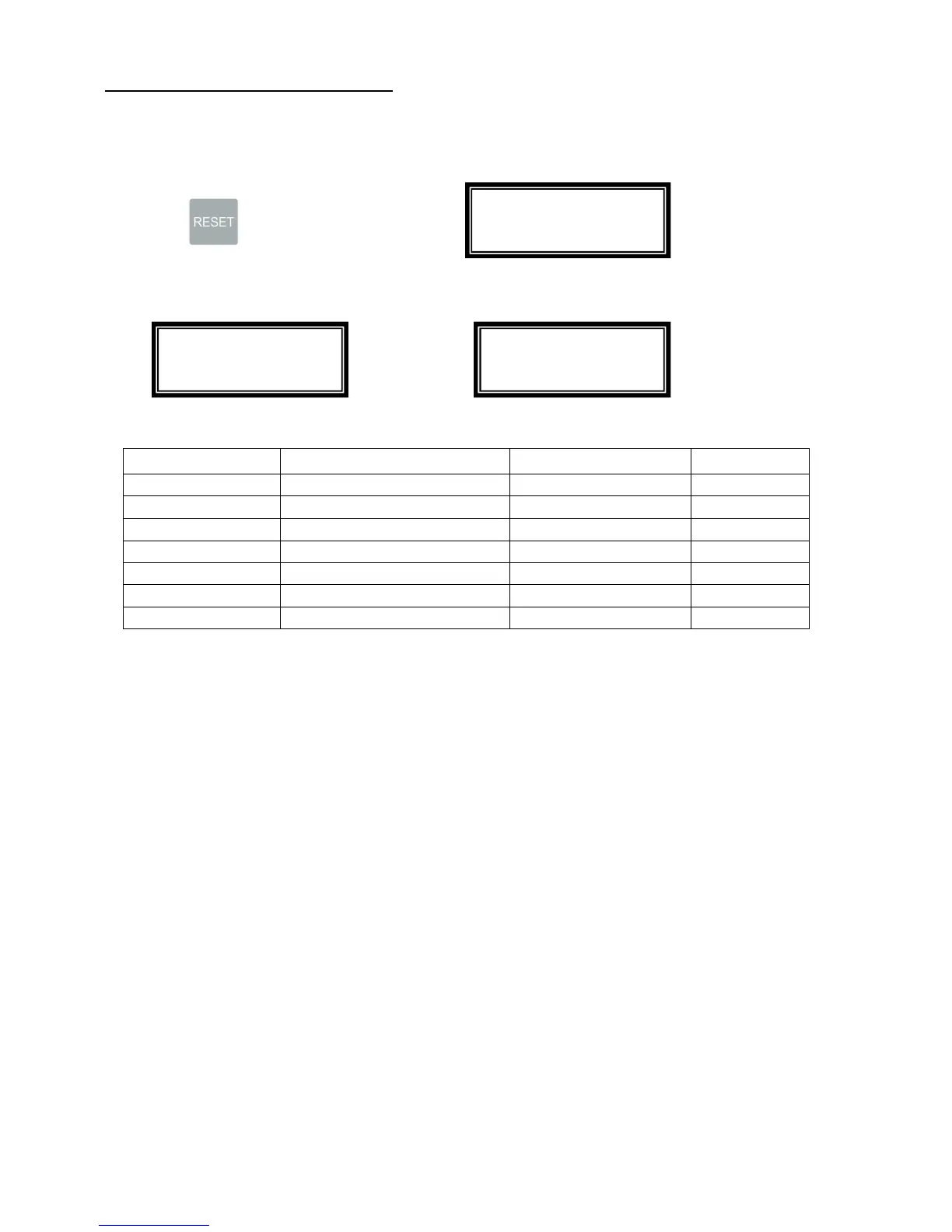
1. Hold then turn the power to on, is displayed
2. Using a piece of paper to trigger the sensor, the sensor on the interface board connection are
showing as below. Remove the trigger, the display will change to
, If the display remains, it means that
sensor is bad.
Sensor
Function Board Connection
Connector #
S1 Feed Tray Sensor Interface Board I – 20
S2 Input Sensor Interface Board I – 21
S3 Paper Monitoring Sensor Interface Board I – 23
S4 Mark Reading Sensor Interface Board I – 22
Top cover Safety Switch Logic Board L – 11
Rear Cover Safety Switch Logic Board L – 14
Wast Bin Safety Switch Logic Board L – 15
Firmware Version: 01
Sensor Scan: OK
Firmware Version: 01
Sensor Scan: OK
Firmware Version: 01
Sensor Scan: I-20
 Loading...