Instruction Book
Effective: November 2017 Page 28
For more information visit: www.Eaton.com IB131016EN
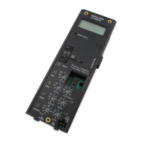
Figure 4-13 Drawout Cassette with Primary Safety
Shutters Open Showing Fixed Primary Stabs
back of the cassette (Figures 3-7, 3-9 and 4-13). Proper
engagement (fully engaged) of the finger clusters
(disconnects) and the cassette stabs takes place as the
circuit breaker is levered into the fully CONNECTED
position, as described next in paragraph 4-6.4. The
primary safety shutters automatically move out of the way
as the circuit breaker is levered toward the CONNECT
position exposing the fixed primary stabs in the cassette.
The primary safety shutters also close automatically as
the circuit breaker is levered toward the TEST position.
Refer to the next paragraph 4-6.4 levering details and
additional safety shutter information.
4-6.4 LEVERING CIRCUIT BREAKER
CAUTION
MAKE SURE THE CIRCUIT BREAKER ELEMENT IS
IN THE FULLY RACKED OUT POSITION IN THE
CRADLE BEFORE ANY ATTEMPT IS MADE TO PUT
THE CIRCUIT BREAKER INTO THE CASSETTE.
FAILURE TO DO SO COULD RESULT IN EQUIPMENT
DAMAGE OR BODILY INJURY DURING LIFTING AND
HANDLING. REFER TO PARAGRAPH 4-6.2 FOR
CIRCUIT BREAKER POSITIONING DETAILS AND
SEE FIGURES 4-14 AND 4-15.
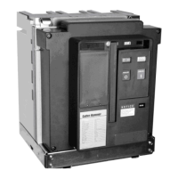
Figure 4-14 Circuit Breaker Shown in Levered Out
DISCONNECT Position - Correct for Breaker Positioning
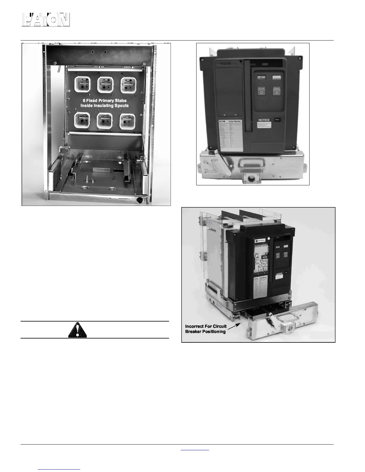
Figure 4-15 Circuit Breaker Shown in Levered In
CONNECT Position - Incorrect for Breaker Positioning
The purpose of the levering device is to move the circuit
breaker from the TEST position to the CONNECT position
and from the CONNECT position to the TEST position. The
mechanism is comprised of a drive screw and nut, and is
part of the lower cradle assembly (Figure 4-16).
 Loading...