Instruction Book
Effective: November 2017 Page 44
For more information visit: www.Eaton.com IB131016EN
5-5 ELECTRONIC TRIPPING SYSTEM
VCP-T and VCP-TR circuit breakers utilize a three part
tripping system:
Microprocessor-based trip unit
Current Sensors
Trip Actuator
All three parts of the tripping system are discussed here,
except that the trip unit itself is not discussed in detail.
For detailed information pertaining to the different trip
unit models available with these circuit breakers, refer to
the specific instruction leaflet dedicated to the trip units.
5-5.1 MICROPROCESSOR-BASED TRIP UNIT
VCP-T and VCP-TR circuit breakers can use either of
two Digitrip RMS trip units whose main features are
summarized in Table 5.1. The two models (Model 520V
and Model 1150V) are not interchangeable in the field.
Contact Eaton for upgrading to Model 520V or Model
1150V.
The electronic trip units are self-powered. When the
circuit breaker is closed, no external power is required
to operate their protective systems. Current signal levels
and the control power are derived from the current
sensors mounted behind the cassette.
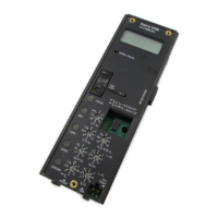
Table 5.1 Digitrip Trip Units
Functions 520V
1150V
`
LSIG Protection Yes Yes
Disable
Yes Yes
GF Protection Yes Yes
GF Alarm No Yes
Display No Yes
‹
Programmable No Yes
Metering No Yes
Power and
Energy Values
No Yes
Power Quality No Yes
Communication No Yes
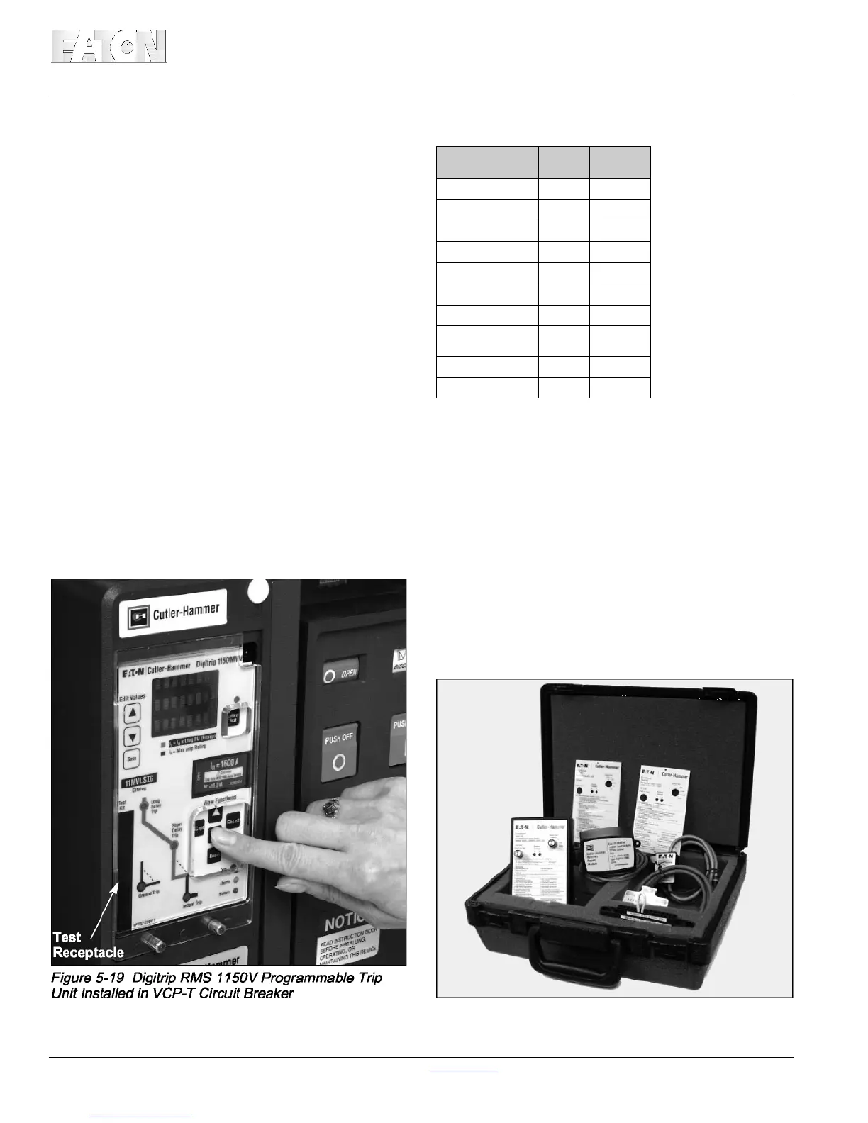
Three-line, (eight characters per line) LED display.
Available control voltages are 24/48Vdc, 1 20Vac and 240Vac
A functional local test can be performed through the trip
unit’s test receptacle (Figure 5-19). A small hand held
functional Test Kit is used to check circuitry and
mechanical tripping functions (Figure 5-20).
When the circuit breaker is shipped from the factory, the
trip unit’s protective functions are normally set at
minimum values. For specific overload tripping
characteristics and time/current curves to coordinate
with a load or system, refer to the trip unit instruction
book.
Figure 5-20 Hand Held Tester
 Loading...